
Related Manuals for Testifire 1000 Series


Summary of Contents for Testifire 1000 Series
- Page 1 � · � !@ ! ! l.f USERMANUAL JQQQSERIES o o o o ílm www.sdifire.com/testifire...
- Page 2 To protect the high-precision technology contained in Testifire, read the appropriate sections of the U ser Manual to never leave Testifire in the places listed below, whether if in use understand the nature and severity of ali the potential or in storage: hazards present and the action you must take.
-
Page 3: Table Of Contents
3.3 INSERTING I I .3 REMOVING 'º STARTED THE MEMBRANE GETTING REPLACING & ACCESSORIES 4. I POWERING ON TESTIFIRE I 2 CONSUMABLES INTERFACE & MAIN MENU I 3 TECHNICAL SPECIFICATIONS & HEAD UNIT ANGLE 4.3 ADJUSTING I 4 TROUBLESHOOTING SUPPORT TESTING HIGH PROFILE DETECTORS 4. -
Page 4: General Instructions
EU Directives for CE marking: not in use. • EMC Directive 2014/30/EU of the European Parliament and Do not use Testifire or Solo poles if they are damaged in any way. of the Council of 26 February 2014 on the Contad if in any doubt. - Page 5 T hank y ou for p urchasin g the Testifire Multi-Sensor Detector Tester This manual is designed to assist you to get the best and most efficient use of the Testifire 1 000 series and provides ali the information required to perform routine service and maintenance tasks with ease.
- Page 6 KIT CONTENTS TESTIFIRE 1001-1 SMOKE, HEAT KIT CONTAINING: t¡ � l l D � lx TS3 SMOKE CAPSULE íl íl íl íl íl íl lx SOLO 727 CHARGER lx TESTIFIRE 1000 HEAD UNIT www.sdifire.com/testifire...
- Page 7 TESTIFIRE 1001 SMOKE, HEAT KIT CONTAINING: � □ � 1x TS3 SMOKE CAPSULE íl íl íl íl íl íl 1x SOLO 727 CHARGER lx TESTIFIRE 1000 HEAD UNIT www.sdifire.com/testifire...
-
Page 8: Preparation For Use
3 PREPARATION FOR USE 3.1 CHARGING THE BATTERY 3.2 INSERTING THE BATTERY & Solo NiMH Battery Batons are used to power Testifire and enable it to be fitted to Solo Access Poles. CAUTION & ENSURE CORRECT ORIENTATION WHEN INSERTING WARNING THE BATTERY BATON INTO TESTIFIRE. -
Page 9: Inserting The Smoke Capsule
ílílílílílílíl íl NOTE Smoke Capsules are non-refillable. Only replace with genuine Testifire TS3 Smoke Capsules. lt is recommended the capsule should be removed from the unit when not in use for a few days. �... -
Page 10: Getting Started
Fran9ais Select Cancel NOTE lf not used within 16 days or when a Smoke Capsule has been replaced, Testifire will self-prime at power-on, prior to displaying the main menu. This is lndicated by a message 'Preparing for use' NOTE lf the unit is left in Stand by mode for more than 5 minutes, it will power off to conserve the battery. -
Page 11: Interface & Main Menu
LED REFERENCE CHART • TESTLED STATUS LED • Flashing Slow Flashing Green/Red Green Blue Smoke ldle Mode Testifire T imeOut Flashing Fast Green = Red= Heat Operational Mode Flashing Red Clear Clearing Battery requires charging Flashing Blue/Red Salid Red... -
Page 12: Adjusting Head Unit Angle
The inner clear cup has a semi-circular cut-out on the side nearest to the user interface. Place your flnger in the cut-out and carefully lift out the cup. This will allow for corred positioning of the high proflle detector within the cup. .sdifire.com/testifire... -
Page 13: Single Test
After you have completed the preparation An infrared beam across the clear cup When the detector is activated, procedures, Testifire will be ready for use. controls the test. The test will begin remove Testifire by lowering it gently. automatically when the head unit is Testifire will return to idle. -
Page 14: Heat Testing
Heat. The T est LEO when the head unit is placed over the remove Testifire by lowering it gently. will turn Red, indicating Testifire is ready to detector, breaking the infrared beam. Testifire will return to idle. -
Page 15: Clearing Adetector
The test LED will not illuminate during clearing. NOTE Clearing has a maximum time of 2 minutes. After 2 minutes Testifire will timeout, highlighted by the status LEO flashing Red/Green Set Clear as part of a sequential test with Smoke e.g. Smoke is 1 and Clear is set to 2. -
Page 16: Sequential Testing
6 SEQUENTIAL TESTING Using Testifire to carry out a Sequential Test means that a number of operations (Smoke, Heat and Clearing) can be pre-programmed into the unit before it is raised up to the detector. This saves time, reduces handling and enables the testing of certain multi-sensor detectors. - Page 17 [Heat J, Smoke 2, Clear 3]. Or [Smoke J, Clear 2, Heat 3]. When the detector is activated, remove Testifire by lowering it Lower Testifire once the detector has been cleared. gently. After 2 seconds raise again to begin clearing Testifire will return to idle.
- Page 18 ► Smoke 1 Smoke 1 Heat Heat 2 ► Clear Clear Menu Status Menu Status .sdifire.com/testifire...
- Page 19 When the detector is activated, remove Testifire by lowering it Lower Testifire once the heat test has completed. gently. After 2 seconds raise again to begin the heat test Testifire will return to idle. LOWERFOR 2SECONDS NOTE lf the detector does not re-enter the cup within I O seconds, the test sequence will reset and return to the first test of the programmed sequence.
- Page 20 ► Smoke 1 Smoke 1 Smoke 1 Heat Heat Heat 3 ► Clear Clear 2 ► Clear 2 Menu Status Menu Status Menu Status .sdifire.com/testifire...
- Page 21 T he initial smoke test will begin automatically When the detector is activated, remove Testifire by lowering it when the head unit is placed over the gently. After 2 seconds raise again to begin clearing detector. Breaking the infrared beam.
-
Page 22: Simultaneous Testing
7 SIMULTANEOUS TESTING/ MULTI-SENSOR TESTING Using Testifire to carry out a Simultaneous Test means that a number of operations (Smoke, Heat) can be pre-programmed into the unit before it is raised up to the detector. T his saves time, reduces handling and enables the testing of certain multi-sensor detectors if they are so enabled. -
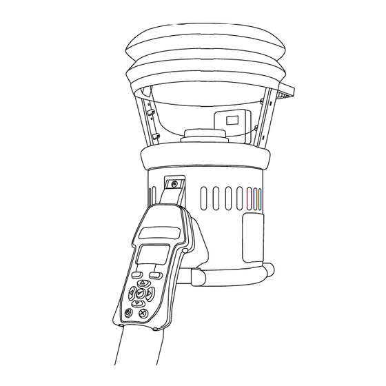
Page 23: Testifre Infrared Remote Control
Aim the infrared beam LED at the Testifire head unit when it is at height and use the operation button on the lnfrared Control Unit to start/stop a test. -
Page 24: Settings
Press the menu key to enter the sub menu. System information will display the Model, Find further information on the website ► Smoke or contad Testifire support by emailing Serial Number, Software Version and the Heat service@sdifire. c om. Hardware Version. Warranty information Clear can also be viewed. - Page 25 ► ► SERVICE SYSTEM RESET Testifire used to have a Service reminder message which Restare Testifire to factory default settings. A has since been disabled. For older units, if a message System Reset will remove all user customisable on the screen shows 'Service Required', but the unit is...
-
Page 26: Removing & Replacing Consumables
10.1 REMOVING THE SMOKE CAPSULE Open the access cover on the Squeeze the tvvo clips on each side of the used body of the Testifire. capsule and gently pull the capsule out. 10.2 REPLACING THE SMOKE CAPSULE Remove the spring clip protector Holding the capsule by the spring clips Close the access cover securely. -
Page 27: I 0.4 Replacing The Battery
UNDUE FORCE TO INSERT. REMOVE BATTERY FROM TESTIFIRE WHEN NOT IN USE. Hold the Testifire head unit by the handle and press the upper spring button on the Battery Baton. Align the button with the location hole in the handle and push the Battery Baton into the handle until the button springs up through the hole. -
Page 28: I I Removing & Replacing Spares
11.2 REPLACING THE CLEAR CUP Hold the clear cup using the cut-out, Line the cup with the rectangular cut-out in line with and pull up firmly. the smoke/heat duct. Press the cup down from the middle until it clicks into place. .sdifire.com/testifire... -
Page 29: I I .3 Removing The Membrane
Line up the membrane with the two flat supports nearest the smoke/heat duct. Work the membrane round the plastic cup, making sure the cup fits into the slot in the membrane. Finally, pull the membrane over the last edge of the cup. www.sdifire.com/testifire... -
Page 30: Accessories
12 CONSUMABLES & ACCESSORIES Use only approved accessories that are recommended by the manufacturer for your Testifire model. Testifire does not contain any field serviceable parts. The following spare and consumable parts are available to order from your distributor. Ordering lnformation... -
Page 31: I 3 Technical Specifications
Power Source Battery Baton: nominal 7.2V 3.0Ah NiMH rechargeable battery pack with interna! overcurrent protection connects directly to Testifire with no leads or wires. Must be charged by Solo 727 Battery Charger (using 100-230VAC or 12VDC input). Battery Charge Time Approx. -
Page 32: I 4 Troubleshooting & Support
In sorne cases the error message may be cleared from the screen by pressing the escape key. T his may enable the unit Do not use Testifire or Solo poles if they are damaged in any way. Contact service@sdifire.com if in any doubt. - Page 33 www.sdifire.com/testifire...
- Page 34 3535 State Highway 66 Parkway 100 Building 6 Neptune, NJ 07753 aamm www.sdifire.com/testifire Tel: 732-751-9266 sales@sdifire.com www.sdifire.com h our policy is one of continuous improvement, details of products described within this publication are subject to change without notice. AII information provided here is believed to be corred at the time of going to press.
Need help?
Do you have a question about the 1000 Series and is the answer not in the manual?
Questions and answers