Table of Contents
Advertisement
Quick Links
Advertisement
Table of Contents

Related Manuals for Cerlic CBX


Summary of Contents for Cerlic CBX
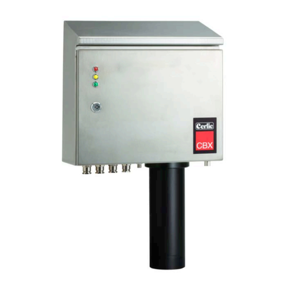
- Page 1 Cerlic CBX Sludge Blanket Monitor 2011-11-08 C81B5EN12...
-
Page 2: Table Of Contents
System ....................................12 Timer ....................................13 INFORMATION DISPLAY ..........................13 PROFILE ................................14 .................................. 16 ALIBRATION Calibration of sensor ..............................16 DEITAILED INFORMATION OF CBX ......................17 Main control board ................................17 ................................17 ICKUP BOARD Axle board ..................................18 Sensor....................................18 Cable drum assembly ..............................19... - Page 3 Cable and sensor ................................24 ............................... 25 ROUBLESHOOTING ....................................25 LARM APPENDIX 1, MOUNTING OF CBX SUPPORT STAND ................26 APPENDIX 2, MOUNTING OF FLUSH PIPE ..................... 27 APPENDIX 3, WIRING DIAGRAM ......................28 APPENDIX 4, SAFETY INSTRUCTIONS ....................29 CONTACT INFORMATION ........................... 30 WARRANTY ..............................
-
Page 4: General Information
Description of the function CBX is an optical suspended solids meter designed to measure sludge and fluff blanket depth in clarifiers, thickeners, etc. in water and wastewater plants, as well in other facilities. -
Page 5: Installation
Cerlic. Packing The original packing is designed to protect the equipment and should be used for storage or if the goods must be returned. If other packing material is used Cerlic is not responsible for damages during transport. Content Please check that the content corresponds to your order and packing list. -
Page 6: Starting Up
This will not damage the instrument but the automatic cleaning function will stop working. It is also recommended to use a CBX Jacket (P/N 11205969) when there is a risk of temperatures below 23ºF (-5ºC). -
Page 7: User Interface
User interface The BB1/BB2 will show the CBX as a standard “X” sensor on the display and it will show both sludge and fluff level in text on the display. Configurations The figure below shows the different terms used for distances that are involved in the configuring of the CBX. -
Page 8: Operation
If the CBX for some reason does not retract the cable, then it is possible to do manually. But always try to switch off the main power to the CBX for 10 seconds and then back on line again. The CBX will always start with retracting the cable to “home position” after a power loss. -
Page 9: Configuration Terms
fghj Configuration terms Home position, A The sensor will always return to this position. Blind zone, B Sludge or foam detected in this zone during lowering of the sensor is not registered. Unwanted interference is prevented by setting this zone to be 1’ (0.3m) below the normal liquid surface. -
Page 10: Bb1/Bb2 Menu For Cbx
BB1/BB2 menu for CBX This section describes the menus used in BB1/BB2 to set up the CBX for operation. ! Important, you need to exit the Settings menu to save the parameters or changes! Settings Name of the sensor (10 characters) shown on the main display. -
Page 11: Cbx Setup
Track Profile/Level. You can set if the CBX shall measure sludge profile or only sludge and fluff levels. If the CBX is set to Level the sensor will stop when it detects the sludge level and return home. Calibration... -
Page 12: Cleaning
Enables the BB1/BB2 to control the sensor in the Manual up/down CBX to go UP and DOWN. In this mode the sensor is switched off and can be left out for an unlimited time for cleaning. Must change “MODE” to “TRIG”... -
Page 13: Timer
Relay Relay 1/ Relay 2, can be used as level alarms. You can configure one of the internal relays as a timer to start the CBX if you do not have a rake to use as a trigger. Next time... -
Page 14: Profile
Profile CBX users can get the sludge profile using the 4 output signals on the BB2. It is updated at the end of each sampling cycle (channel 3 & 4 are on-line during sampling). This option requires an extra card in theBB2 unit with two more 4-20mA signals (total 4 outputs) Attach the extra mA card to the BB2 (P/N 11905782) see appendix 6. - Page 15 fghj Profile data fig 4...
-
Page 16: Calibration
The CBX will collect samples and the BB1/BB2 shows this with a pop-up window. 5. In the case of sludge calibration enter the “Sample” concentration from the lab test. 6. Set the CBX in Trig mode (Calibration/Modes) and back out of the menu to save the values or changes. -
Page 17: Deitailed Information Of Cbx
Deitailed information of CBX The sludge blanket monitor system is constructed from parts built inside a cabinet. The parts are described and illustrated in the sections below. Main control board The main control board controls the mechanical events in the cabinet and communicates with both sensor and BB1/BB2. -
Page 18: Axle Board
fghj Axle board The axle board mounted on the cable drum is powered by contact free power (inductive) from the pickup board. It communicates with the main board via the pickup board and it communicates with the sensor through an optical RS-485 interface. fig 7 Sensor The sensor is connected to a cable that supplies it with power and transmits the... -
Page 19: Cable Drum Assembly
fghj Cable drum assembly The cable drum moves the sensor up and down in the clarifier. It is mounted directly on the axle of a synchronous motor, hidden behind the drum mounting plate, with a very constant speed. Since the diameter of the cable roll in the drum varies, the speed of the sensor will vary. -
Page 20: Heater & Fan
There is also an emergency motor control switch that is located on the box for the terminal block inside the CBX. The switch can be located on top of the terminal box or under the lid, fig 12. fig 12... -
Page 21: Appendix 6 , Optional 4-20Ma Output Module For Bb1/Bb2
fghj Appendix 6 , Optional 4-20mA output module for BB1/BB2 Introduction The BB1/BB2 4-20mA module is used to expand the BB1/BB2 central unit from two to four 4-20mA loops. It is assumed that the user is familiar with the BB1/BB2 and 4-20mA technology. - Page 22 fghj Mounting of the 4-20mA expansion card in the BB1/BB2 control box The 4-20mA module shall be mounted in a BB1/BB2 control box. Make sure the power to the control box is switched off before mounting the module. Connect yourself and the control box chassis to protective ground before opening the antistatic package of the module to avoid static discharges that can damage the module or the box.
-
Page 23: Wire Connections
BB1/BB2 menu under Settings / Exp.module. Configure the sensor(s) that shall use channels 3, and 4 to do so in the sensor menu. Technical specification for 4-20mA module Manufacturer Cerlic Controls AB, Sweden Name BB2 4-20mA expansion module Measurement... -
Page 24: Maintenance
It is possible initiate a manual trig of a sample. By holding down the “down arrow” for 5 sec on the BB1/BB2. The CBX starts a sampling cycle ASAP and returns the sensor back home and normal mode. If more then one sensor (BB2) is connected this function will be disabled. -
Page 25: Troubleshooting
It may stop the operations of the CBX and it is reset by pressing ENTER on the BB1/BB2. SENSOR TILT means that the sensor has tilted more than 45 degrees and the tilt switch in the sensor has detected this. -
Page 26: Appendix 1, Mounting Of Cbx Support Stand
Appendix 1, Mounting of CBX support Stand The support consists of two brackets, left and right hand, and a crossbar brace. Assemble the parts according to the figure. Hang the assembly on the handrail with the 1 ½” u-bolts or special L brackets for 4” or 6”... -
Page 27: Appendix 2, Mounting Of Flush Pipe
Connect a hose or pipe of at least 10mm (3/8”) diameter to fitting. The water pressure must not exceed 6 bars (90 psi). A last check before starting the CBX: 1. Check that the sensor cable is properly wound on drum and cable guide. -
Page 28: Appendix 3, Wiring Diagram
Appendix 3, wiring diagram Connection box for power supply & rake limit switch Rake limit contact N/O Contact 24VDC from CBX fig 16 Connection terminals for control board fig 17... -
Page 29: Appendix 4, Safety Instructions
Appendix 4, Safety instructions The CBX is designed and manufactured with the greatest possible safety. It meets state-of-the art safety requirements and all relevant recommendations and standards. The instrument is CE marked and follows EU directives and standards as listed below. -
Page 30: Contact Information
Instruments delivered from Cerlic Controls AB, are carefully checked and tested prior to the shipment. Cerlic warranty repair of the CBX if it is determined that the problem is any fault in manufacturing or equipment during the warranty period. The warranty period is 12 months from the date of invoice. -
Page 31: Specification, Cbx
Full power below 5 ºC (41°F), Off above 15 ºC (59°F) Storage temp -20 to +60 ºC (-4°F to 140°F) Rake Limit Switch Closing contact normally open, 24VDC is supplied from CBX. Sensor Waterproof to 10m (30 ft.) in stainless steel 2343 with cable in Motor... -
Page 32: Dimensions In Mm (")
fghj Dimensions in mm (“) fig 18... -
Page 33: Appendix 7, Service Form
Appendix 7, Service Form Service form Cerlic products are characterized by a high degree of quality and functionality. In the unlikely event of difficulties, please fill out this form, and if available, the support information form available as appendixes in the manuals. Please have the information at hand when contacting Cerlic service to verify the problem or before sending the product for service. -
Page 34: Appemndix 8, Setup Form
fghj Appendix 8, Setup Form This sheet can be used to document the setup of a sensor. Sensor Type _____________________________________________________ Position / Tag _____________________________________________________ In the System sub menu of the sensor menu the following information can be collected. Serial _____________________________________________________ SoftW _____________________________________________________...
Need help?
Do you have a question about the CBX and is the answer not in the manual?
Questions and answers