Table of Contents
Advertisement
Quick Links
Advertisement
Table of Contents

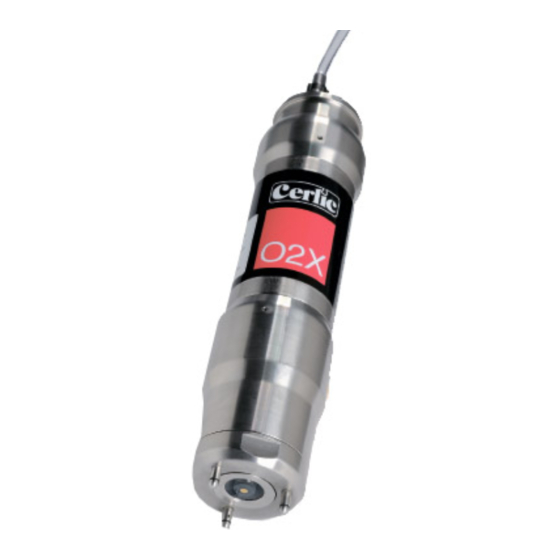
Summary of Contents for Cerlic O2X
- Page 1 Dissolved Oxygen Sensor 2002-11-18 MANE11/02 Ver 2.00...
-
Page 2: Table Of Contents
A few words about this manual Design Measuring principle Unpacking the sensor Damages Packaging Content Optional parts for O2X Dissolved Oxygen sensor: Mounting the sensor Cable Connections Installation Tips Removing the sensor Changing or Installing a new electrode Removing an old electrode:... -
Page 3: Introduction
The electrode housing is made of PVC. An O-ring on the electrode prevents water from leaking into the O2X. A six-pin connector of the back of the electrode connects to the O2X. -
Page 4: Unpacking The Sensor
Please check that the content corresponds to your order and packing list. Every shipment should include: • O2X sensor P/N: 11305473, including 33 ft. (10 m) cable and 33 ft. (10m) flushing hose. You will also need an electrode (below) to get the sensor working: Optional parts for O2X Dissolved Oxygen sensor: •... -
Page 5: Mounting The Sensor
Mounting the sensor The O2X is mounted on a telescopic fibreglass rod and placed in a mounting bracket that fastens to a handrail, please refer to the Appendix 1 for further details. As an alternative way of mounting the sensor, an adjustable slide rail holder is available, please refer to the Appendix 2 for further details. -
Page 6: Removing The Sensor
Removing the sensor The sensor is removed in the following steps: • Disconnect the sensor cable from the BB2 and the flushing hose from solenoid. • Open the clamp, and pull the rod out of the mounting bracket • Make sure all water inside the rod is drained. •... -
Page 7: Installing A New Electrode
Installing a new electrode: • Untighten the flushing head about one turn (if not already lose) to let the air out when the electrode is pushed in place. • Plug the electrode cable into the connector on the electrode. • Install the new electrode into the flushing head. Do not touch the membrane of the electrode when mounting. -
Page 8: Cleaning Unit
BB2 control box. Flushing must be activated in the “Settings” menu in the BB2 control box: • Select the O2X transmitter in the Main Menu by using the buttons. • Press ENTER for approximately five seconds to enter the Transmitter Menu. -
Page 9: Mounting Plate For Solenoid Valves
Mounting plate for solenoid valves To provide an easy mounting of solenoid valves for the built- in flushing nozzles Cerlic offers a predrilled Aluminum handrail mo unting plate. The Mounting plate is fixed to the rail using two u-bolts. Please see technical specifications for details and ordering information on Solenoid Valves and Mounting Plate. -
Page 10: Menu For O2X Transmitter
Cleaning Press ENTER to go to Cleaning program Cleaner ”None”, ”Flush”, or ”Brush”. Do not select “Brush” since this does not exist for O2X sensor Interval min 0-999 minutes, time between cleaning cycles Length sec 0-999 seconds, duration of flushing cycle... - Page 11 Temp Sensor temperature, read only Info Press “ENTER” to go to “info” read only menu. This menu is for Cerlic internal use, it may change without notice SA value for zero sample SA value for air sample Cons 1 Calculated concentration at last air calibration...
-
Page 12: Calibration
Refer to “Section 8 – Changing or installing a New Electrode”. Zero calibrating a sensor: • Select the O2X transmitter in the Main Menu by using the buttons. • Press ENTER for approximately five seconds to enter the Transmitter Menu. -
Page 13: Air Pressure Conversion
compare the current dissolved oxygen value with setvalue (see below for description). The unit returns to the menu when the calibration is finished. The following appear in the Calibration menu as read-only: • Temp (info): Displays the current temperature of the sensor. •... -
Page 14: Scaling
12. Scaling The “SCALE” menu (see the BB2 manual) allows the user to set the high and low boundaries for a 4-20mA output signal. In addition, this menu allows the user to set high and low alarms values that can be used to notify when the level has reached critical points. -
Page 15: Technical Description
The Sensor has been developed and manufactured in accordance with the following standards: SS-EN50 082-2 (immunity), SS-EN50 081-2 (emission), SS-EN61 010-1 (safety) 89/336/EEC, 92/31/EEC, 93/36/EEC, 73/23/EEC Optional parts for O2X Dissolved Oxygen Sensor: • Electrode cartridge. P/N: 11805160 • Mounting bracket X, including rod holder P/N 11205539 •... -
Page 16: Dimensions
14. Dimensions - 16 -... -
Page 17: Appendix 1, Assembly Of Handrail Mounting Kit
Appendix 1, Assembly of handrail mounting kit • Mount the Flexible Mounting Bracket on existing handrail or on separate holder. The bent lip on the mounting plate shall be on top and faced toward the liquid or tank. Adjust the Mounting Bracket to the correct angle and tighten the nuts. -
Page 18: Appendix 2, Assembly Of Adjustable Slide Rail
Appendix 2, Assembly of adjustable slide rail - 18 -... -
Page 19: Appendix 3, Support Information
Appendix 3, Support information Before calling Cerlic support, please collect the information in this form and have it at hand. Company _____________________________________________________ Name _____________________________________________________ Phone _____________________________________________________ E-mail _____________________________________________________ Sensor Type _____________________________________________________ Position / Tag _____________________________________________________ First go to the BB2 menu, it is accessed by pressing and ENTER at the same time for five seconds. -
Page 20: Appendix 4, Setup Information
Appendix 4, Setup information This sheet can be used to document the setup of a sensor. Sensor Type _____________________________________________________ Position / Tag _____________________________________________________ In the System sub menu of the sensor menu the following information can be collected. Serial _____________________________________________________ SoftW _____________________________________________________ In the Settings sub menu of the sensor menu the following parameters can be set.


Need help?
Do you have a question about the O2X and is the answer not in the manual?
Questions and answers