Table of Contents
Advertisement
Quick Links
Advertisement
Table of Contents

Related Manuals for Cerlic CBX


Summary of Contents for Cerlic CBX
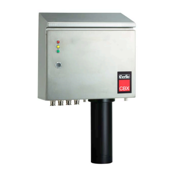
- Page 1 Cerlic CBX Sludge Blanket Monitor 2017-12-15 C81E5EN18...
-
Page 2: Table Of Contents
Electrical connection ..............................7 ................................8 SER INTERFACE Sludge rake guard limit switch, Trigger ........................ 7 CBX ................ 8 ESCRIPTION OF IMPORTANT DISTANCES WHEN INSTALLING Home position, A ................................9 Blind zone, B ..................................9 Max depth, C ..................................9 Sludge level, D .................................. - Page 3 DETAILED INFORMATION OF CBX ....................17 ..................................... 18 ENSOR Main control board ................................17 Cable drum assembly ..............................18 .........................................18 Heater & fan ..................................19 .........................................19 Flushing tube & valve ..............................19 Connection terminal ..............................19 5. SAFETY INSTRUCTIONS, CE MARKING ....................20 MAINTENANCE ............................20 Manual operation of CBX ............................21...
-
Page 4: General Information
The cable or the sensor must not be touched while it is going up or down (pinching). CBX noise level is below 70 dB(A). CBX is an optical suspended solids meter designed to measure sludge and fluff blanket Description of the function depth in clarifiers, thickeners, etc. -
Page 5: Installation
The original packing is designed to protect the equipment and should be used for Packing storage or if the goods must be returned. If other packing material is used Cerlic is not responsible for damages during transport. Please check that the content corresponds to your order and packing list. -
Page 6: Mechanical Installation
Leveling screws Mount the CBX so there is no risk that the sensor will be stuck in something on the way down in the basin. This is extra important for outdoor installations where wind can make the sensor swing so much that it is a risk that it will stuck for example a hand railing. -
Page 7: Water Connections
If emergency winding/unwinding is to be performed, use the up / down switch. NOTE! Binding risk between cable drum and droplet drainage. CBX can be installed in an environment where a moving rake is being used. This is done Sludge rake guard limit switch, Trigger by installing a border contact, closing (NO), which is controlled by the scraper’s... - Page 8 (alarm) or ongoing measurement. The Control Box (BB1/BB2) will show the CBX as a standard “X” sensor on the display User interface and it will show both sludge and fluff level in text on the display. If only one sensor location is used on the Control Box, CBX will display the previous sludge level, concentration and depth in real time during soldering.
-
Page 9: Home Position, A
The fluff layer or depth found when the present fluff concentration is reached. Fluff, G Turn on power to the device. Installation, software Set the CBX in configuration mode, using the control panel: Configuration mode CBX → Calibrate → Mod → Conf Menu path The green LED on the door should now blink. -
Page 10: Advanced Settings (Defaults)
CBX will make an automatic adjustment to the height of the scrapers, after a correct ”Rake Height” has been noted. -
Page 11: Ode
There is two different modes the CBX can be set to, Setup and Trig. CBX Mode Trig is the normal working mode. In this mode the CBX will take a sample on every external trig from the rake limit switch. -
Page 12: Save And Exit
Emergency retraction of the cable But always try to switch off the main power to the CBX for 10 seconds and then back on line again. The CBX will always start with retracting the cable to “home position” after a power loss. -
Page 13: Bb1/Bb2
BB1/BB2 menu for CBX This section describes the menus used in BB1/BB2 to set up the CBX for operation. ! Important, you need to exit the Settings menu to save the parameters or changes! Settings Name of the sensor (10 characters) shown on the main display. -
Page 14: Cbx Setup
Profile/Level. You can set if the CBX shall measure sludge profile or only sludge and fluff levels. If the CBX is set to Level the sensor Track will stop when it detects the sludge level and return home. -
Page 15: Cleaning
Relay 1/ Relay 2, can be used as level alarms. You Interval min can configure one of the internal relays as a timer Relay to start the CBX if you do not have a rake to use as a trigger. Next time the sample starts Next time... -
Page 16: Information Display
Change ”MOD” value from ”Trig” to ”Conf” confirm with ”ENTER”. The green LED lamp on the door starts to flash. The display now shows Measured value display. 2. Enter the CBX menu again by pressing ”ENTER” for five seconds. Chose Calibrate again. Now it says “Mod” on ”Conf” (configurate). -
Page 17: Main Control Board
Exit all menus back to measuring value display again. The sludge blanket monitor system is constructed from parts built inside a cabinet. The 4. Detailed information of CBX parts are described and illustrated in the sections below. -
Page 18: Cable Drum Assembly
fghj The main control board controls the mechanical events in the cabinet and communicates with both sensor and BB1/BB2. The BB1/BB2 communication is done through RS-485 interface. Other signals going in and out of the cabinet are also connected to the main control board. -
Page 19: Heater & Fan
There is also an emergency motor control switch that is located on the box for the terminal block inside the CBX. The switch can be located on top of the terminal box or under the lid, fig 12. fig 12... -
Page 20: Safety Instructions, Ce Marking
The instrument is CE marked and follows EU directives and standards as listed below. Installation of the equipment should be done by authorized personnel only. CBX may not be installed so that the safety of the plant is affected or where there is a risk of explosion. -
Page 21: Manual Operation Of Cbx
It is possible initiate a manual trig of a sample. By holding down the “down arrow” for 5 Manual operation of CBX sec on the BB1/BB2. The CBX starts a sampling cycle ASAP and returns the sensor back home and normal mode. If more then one sensor (BB2) is connected this function will be disabled. -
Page 22: Clarm Troubleshooting
Visual check of the lenses. Clean with Cerlic (CSC) sensor cleaning liquid and use a soft Sensor lenses. rag if necessary. Check for build up or “film” on lenses. Air filter, remove the cover from the outside and check the filter. The air filter might need to be replaced or cleaned if the equipment is installed in a dusty environment. -
Page 23: Ests
The cable between BBX and CBX not properly fixed • BBX not restored before initial connection to CBX • BBX and CBX not restarted at the same time when first switched on • Measurement over time shows high Too low of threshold is entered •... -
Page 24: Control Of Max Value
Instruments delivered from Cerlic Controls AB, are carefully checked and tested prior to 8. Warranty the shipment. Cerlic performs warranty repair of the CBX if it is determined that the problem is of any fault in manufacturing or equipment during the warranty period. -
Page 25: Specification, Cbx
Full power below 5 ºC (41°F), Off above 15 ºC (59°F) Storage temp -20 to +60 ºC (-4°F to 140°F) Rake Limit Switch Closing, contact normally open. 24VDC is supplied from CBX. Sensor Waterproof to 10m (30 ft.) in stainless steel 2343 with cable in Motor... -
Page 26: Spare Parts And Options
• Solenoid Valve 230V 21750710 • Motor 115V 21750924 • Motor 230V 21750925 • Door key 20305403 • CBX Jacket (for cold weather) 11205969 Options • Isolation & heating for flush tube 21705987 • 4-20 mA expansion board 11905782 • Profibus DP module 21705681 11. -
Page 27: Appendix 1, Profile
CBX users can get the sludge profile using the 4 output signals on the BB2. It is updated Appendix 1, Profile at the end of each sampling cycle (channel 3 & 4 are on-line during sampling). This option requires an extra card in theBB2 unit with two more 4-20mA signals (total 4 outputs). -
Page 28: Appendix 2, Service Form
Date: Signature: _____________________________________________________________________________ Send product to: Cerlic Controls AB, Mälarvägen 3, SE-141 71 Segeltorp, Sweden Enclose this Service Form with the goods and also send it by mail to: service@cerlic.se Return to: Company: Address: Postal no and City Country:... -
Page 29: Appendix 3, Setup Form
fghj Appendix 3, Setup Form This sheet can be used to document the setup of a sensor. _____________________________________________________ _____________________________________________________ Sensor Type Position / Tag In the System sub menu of the sensor menu the following information can be collected. _____________________________________________________ _____________________________________________________ Serial Samples...
Need help?
Do you have a question about the CBX and is the answer not in the manual?
Questions and answers