
Related Manuals for MIR Spirolab


Summary of Contents for MIR Spirolab
- Page 1 Spirolab Service Guide Service manual Rev. 1.0 Date issued 30.12.2014 Date of approval 30.12.2014 Rev.1.0 Page 1 of 33...
-
Page 2: Table Of Contents
Additional Information ........................................5 1.2.7. Installation ............................................5 1.3. GENERAL ............................................... 5 1.3.1. Technical Data ........................................... 5 1.3.1.1. Spirolab unit ............................................5 1.3.1.2. Battery charger ........................................... 6 1.4. STANDARDS APPLIED ........................................6 HARDWARE DESCRIPTION ......................................6 2.1. MAIN BOARD MODULE ........................................ -
Page 3: Introduction
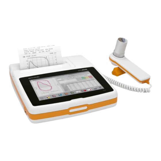
The spirometers from the product group MIR080 are marketed under the label Spirolab. This manual has been written for technicians involved in the service of the Spirolab. Service can be carried out by the service organization of the manufacturer or by any other technician authorized by MIR srl. -
Page 4: Data Registration
Product documentation 1.2.3. The documentation set for the Spirolab includes a User Manual. The User Manual is a recommended item for all service engineers. The user manual is available in the following languages: •... -
Page 5: Additional Information
• the slow Vital Capacity test (VC/IVC) • the Maximum Voluntary Ventilation test (MVV) Spirolab has been designed and manufactured to ensure the highest level of safety and the unit fully complies with the stringent international EN 60601-1 and EN 60601-1-2 standards. -
Page 6: Battery Charger
SANS 451:2008 Spirometry — Generation of acceptable and repeatable spirograms FDA Regulations • Japanese MHLW Ministerial Ordinance 169: 2004 2. HARDWARE DESCRIPTION Because of the modular design of the Spirolab, the description is on a block diagram level. BLOCK DIAGRAM Rev.1.0 Page 6 of 33... -
Page 7: Main Board Module
Charging controller for battery (U5 BQ2004) 2.1.1. The charging controlling circuit used in the Spirolab ensures a charge and optimum condition of the battery providing that the battery temperature and voltage are within the preset limits. Temperature, voltage and time are all monitored throughout the charge process. -
Page 8: Room Temperature Sensor
Oximetry port 2.1.4. Many sensors can be used on Spirolab based on the type of test to be performed and on the patient characteristics. The manufacturer provides the most frequently used sensor with the device, which has the following features: Rev.1.0... -
Page 9: Display Module
2.4. TURBINE FLOWMETER The sensor for measuring flow and volume is similar to the model already used in other spirometers produced by MIR (Series MIR 040 Mod. Spirodoc, MIR024_REV2 Mod. Spirobank G USB, etc). The turbine flowmeter consists of one mechanical and two electrical parts:... -
Page 10: Maintenance
For cleaning of the Spirolab and the accessories please see the User Manual. 3.2. TEST EQUIPMENT For the repair and maintenance procedures of the Spirolab the following test equipment and accessories are required: Complete set of precision engineering tools (including 2.5 mm allen key and cross-screwdriver) Calibration syringe (3L is recommended) Digital multimeter, at least 3½... -
Page 11: Functional Test
Self test 3.3.1.1. Switch on the equipment. Spirolab will carry out the so-called self-test for approx 3 seconds. It is assumed that when the self-test is passed all functions of Spirolab are okay. Any severe malfunction (if any) will be reported on the display. -
Page 12: Cover
Spirolab Service Guide 4.2. Cover The Spirolab case consists of several parts as illustrated in the image beside. The display is housed inside its casing which is made up of two parts held together with three screws. Code 300600 Code 300601... -
Page 13: Pcbs And Components
4.3. PCBs and components Removing and replacing the display 4.3.1. Open Spirolab as described in Paragraph 4.2.1; remove the damaged display from the upper casing. First of all remove the white flat cable from the connector on the rear side of the display (see image), then remove the nuts and the washers from the upper case. -
Page 14: Removing And Replacing The Battery Pack
At this time it is possible to close the device following the instruction described in point 4.2.1 in reverse order. Removing and replacing the battery pack 4.3.2. Open Spirolab as described in Paragraph 4.2.1. To correctly replace the battery pack completely remove double sided tape the PCB from the lower casing. -
Page 15: Removing And Replacing The Thermal Printer
Turbine 4.3.4. There are two types of flow and volume measurement sensors used on Spirolab, single-patient disposable and reusable. Note The Spirolab turbine measurement system is calibrated in the factory and does not require any adjustments or calibrations. -
Page 16: Cleaning The Reusable Turbine
To clean the reusable turbine, first remove it by pulling it gently from the Spirolab turning it anti-clockwise and pressing lightly. It can be helpful to push it gently from underneath with one finger from the bottom of the turbine to lift it out of its housing. - Page 17 To check the connection between the device and the PC, check the correct functioning from the “options, communication” menu. On the display of Spirolab appears the following message: External control To download the new internal software version click on "Tools" menu, and then on "Upgrade Device Internal Software"...
-
Page 18: Oximeter Module
Spirolab Service Guide From the “Select file .tsk” search window select the firmware of your device; click on the Spirolab folder and then on the selected file to automatically launch the upgrading procedure of the internal software of the spirometer. - Page 19 Spirolab Service Guide Table 1 TESTS ON PCB MIR080 WITH OXIMETER Test Procedure Test method Instrument Expected result there should be applied the double sided tape on the The doubled sided adhesives must be applied between Check battery pack application...
- Page 20 Spirolab Service Guide CHECKS ON MAIN CASING OF THE ASSEMBLED DEVICE Table 2 Test Procedure Test method Instrument Expected results Temperature equal to thermometer Temperature Check that the temperature corresponds to the BTPS* Instrument Thermometer reading +/- 1 °C Visual/...
- Page 21 Launch the oximetry test on the MIR device (see Table 3 User Manual). FIVC min/max values, temperature or BTPS function e) Read the value given by the Spirolab (it must be between 83 and 87%). Page 21 of 33 Rev.1.2...
-
Page 22: Testing Procedures For Devices Without Oximeter
Read the value given by the Spirolab (it must be between 93 and 97%). j) Read the heart beat rate on the Spirolab (it must be between 78 e 82). k) Enter the given values in the proper spaces on Annex 1 to this Manual. - Page 23 Spirolab Service Guide Table 4 TESTS ON PCB MIR080 WITHOUT OXIMETER Test Procedure Test method Instrument Expected result there should be applied the double sided tape on the The doubled sided adhesives must be applied between Check battery pack application...
-
Page 24: Spare Parts
Warranty claims 5.2.2. Warranty claims must be provided with the MIR invoice number, the type of products and serial number of the equipment in question. The defective item must be returned back to MIR. The customer is responsible for the transportation and for all transport and customs charges for the delivery of the goods both to and from the service centre. -
Page 25: Troubleshooting
Spirolab Service Guide The unit must be returned in its original packaging. MIR reserves the right to modify the instrument if required, and a description of any modification made will be sent along with the returned goods. Note Any instrument of accessory returned must be accompanied by a clear and detailed explanation of the defect or issue found. -
Page 26: The Device Does Not Measure Spirometry At All
Spirolab Service Guide 6.4. The device does not measure spirometry at all Check if any obstacle is blocking the free rotation of the turbine For information about maintenance cleaning please refer to paragraph 4.3.4.1 of this manual. The VC and MVV tests does not measure –... -
Page 27: Index Of Components
– Check the winspiroPRO USB connection: from menu “Configuration”, “Options”, “Communication” – Check that the driver is installed in the following folder: C:\MIR\winspiroPRO\Drivers\MIR USB drivers\WinVista-Win7 if the driver is not installed then it can be obtained from the manufacturer. Then copy it into the above- mentioned folder. -
Page 28: Appendix A: Spare Parts List
920660 Battery charger 220V/110V Board Code: 891080 Mother board without oxymeter (oxy module) Cable Code: 532362 Cable to connect miniflowmeter to Spirolab New Cable Code: 532361 Micro USB cable for the PC connection Carrying case Code: 672684 Carrying case (grey) -
Page 29: Appendix B: Service Info's (Product Change Notes)
APPENDIX B: SERVICE INFO'S (Product Change Notes) General The technical information in the service manuals of MIR srl is up to date at the date of issue. Necessary additional information (of any kind) will be provided in the following way:... - Page 30 Connettore SMD Zif 10 pin pitch 1.0mm FCI SFW10R-1STAE1LF 124005 Connettore SMD 10PIN (Femmina) per ossimetro CON2 124007 Connettore SMD 10PIN (Femmina) per turbina spirolab IV CON1 125003 Connettore USB tipo A verticale PTH Molex 894858003 Connettore SMD USB series Micro-AB SD-47590-001 top mount (...
- Page 31 Spirolab Service Guide Code Description PCB identification 612080 Transistor MMST2222A SMD SOT 23 (SC59) 612081 Transistor SI1305DL-T1 Vishay CMOS Q7, Q11, Q13, Q20 Q1, Q2, Q6, Q8, Q9, Q10, Q12, Q16, 612082 Transistor SI2302CDS-T1-GE3 Vishay MOSFET Q17, Q18, Q19 630255...
- Page 32 Spirolab Service Guide Code Description PCB identification 712680_0603 Resistenza SMD 0603 0,1W 5% 6K8 R1, R2, R33, R40, R44, R48, R49, R51, 712684_0603 Resistenza SMD 0603 0,1W 5% 10K R58, R60, R68, R86, R87,R88,R89 712692_1_0603 Resistenza SMD 0603 0,1W 1% 22K...
-
Page 33: Annex
Spirolab Service Guide ANNEX 1 Test report form after device repair with oximetry module 2 Test report form after device repair without oximetry module 3 Electrical layout of device 4 Micro Power Oximeter Board Technical Specifications Page 33 of 33...
Need help?
Do you have a question about the Spirolab and is the answer not in the manual?
Questions and answers