
Related Manuals for CR-Tec ER PLUS Series


Summary of Contents for CR-Tec ER PLUS Series
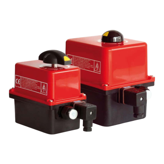
- Page 1 ER PLUS Electric Actuators Installation and Operation Manual 89 lb-in Battery Backup IP66 POSI POSITIONS BBPR 885 lb-in Anticondensation Enclosure protection Duty cycle heater Positioning...
-
Page 2: Table Of Contents
This product meets the European Directive 2012/19/UE about electrical and electronic equipment (DEEE). It mustn't be mixed with common waste. Please, recycle or dispose of them according to your country laws. CR-TEC Engineering Inc. • info@crtec.com • www.crtec.com • 203-318-9500... -
Page 3: Safety Instructions
Do not mount the actuator less than 30 cm of a electromagnetic disturbances source. Do not position the equipment so that it is difficult to operate the disconnecting device. CR-TEC Engineering Inc. • info@crtec.com • www.crtec.com • 203-318-9500... -
Page 4: Position Indicator
1. Turn the knob to position MAN (counter-clockwise) and hold it in position. 2. Turn the outgoing drive shaft of the actuator with the help of an adjusting spanner. 3. In order to re-engage the reduction, release the knob (spring return). CR-TEC Engineering Inc. • info@crtec.com • www.crtec.com • 203-318-9500... -
Page 5: Dimensions
F03/F05-F04 plate Star 14 (mm) Square / Star (mm) Depth (mm) ER35/60/100 Star 22 (mm) ISO F flange Diameter (mm) M threaded Depth (mm) Screws quantity 14.2 14.2 14.2 / 16.4 16.4 CR-TEC Engineering Inc. • info@crtec.com • www.crtec.com • 203-318-9500... -
Page 6: Electric Wiring
To adjust the position of the auxiliary contacts, make rotate the two superior cams by using the appropriate wrench. Re-mount the cover, fasten the four screws and attach the position indicator. CR-TEC Engineering Inc. • info@crtec.com • www.crtec.com • 203-318-9500... - Page 7 Lead Wire. If you are using the Lead Wire type, a jacketed multi-conductor wire is recommended. A rubber grommet is compressed around the jacketed conductor to make a seal. If a tight seal is not important, then any type of wiring can be used. CR-TEC Engineering Inc. • info@crtec.com • www.crtec.com • 203-318-9500...
- Page 8 Open Close IF WIRING TROUGH THE CABLE GLAND FEEDBACK FC1 COMMON FC2 FEEDBACK FC2 COMMON FC1 15V-30V 50/60Hz (12V-48V DC) 100V-240V 50/60Hz (100V-350V DC) — ON/OFF control BBPR compulsory version SNAA690000 CR-TEC Engineering Inc. • info@crtec.com • www.crtec.com • 203-318-9500...
-
Page 9: Electronic Boards
=> check that the valve torque is not superior to the maximum torque stand by the actuator => check that the actuator do not exceed the duty cycle indicated (possible overheat) To re-start the actuator, reverse the sense of rotation or switch the power off and on. CR-TEC Engineering Inc. • info@crtec.com • www.crtec.com • 203-318-9500... -
Page 10: Bbpr Models
-10 °C to +40 °C 1) The auxiliary cables must be connected to inside installation only The factory default configuration is "normally closed" Following a power failure, the BBPR unit will reset after 4 minutes CR-TEC Engineering Inc. • info@crtec.com • www.crtec.com • 203-318-9500... - Page 11 100V-240V 50/60Hz (100V-350V DC) 15V-30V 50/60Hz (24V-48V DC) RS485 Charging Charged battery : contact feedback closed F+ : red wire F- : black wire Failure feedback T+ : yellow wire SNBA130000 Battery unit SNAA690000 CR-TEC Engineering Inc. • info@crtec.com • www.crtec.com • 203-318-9500...
-
Page 12: Posi Models
To proceed to a new setting of the card : please see page 27, “Parameter selection sequence”. To check the proper operation of the card : please see page 27, “Normal operating mode”. CR-TEC Engineering Inc. • info@crtec.com • www.crtec.com • 203-318-9500... - Page 13 For a use with a long power supply wiring, the induction current generated by the wires mustn't be higher than 1mA. The used wires must be rigid (feedback voltages: 4 to 250V AC/DC). CR-TEC Engineering Inc. • info@crtec.com • www.crtec.com • 203-318-9500...
-
Page 14: Parameter Selection Sequence
In the case of an over torque, the motor stops and the 2 LEDS lights then together to indicate the action of the torque limiter. To re-start it, you must either reverse the sense of rotation, either switch the power off and on. CR-TEC Engineering Inc. • info@crtec.com • www.crtec.com • 203-318-9500... -
Page 15: 3-Position Models
Open Open Open FCIO Intermediate open limit switch Auxiliary limit switch 3 Failure report Terminal strip 180° Open Closed Closed FCIF Intermediate close limit switch D1/D2 (24V DC / 3A max) CR-TEC Engineering Inc. • info@crtec.com • www.crtec.com • 203-318-9500... -
Page 16: Technical Data
1 ISO M20 cable gland and 1 DIN43650 3P+T connector Circuit breaker type D, nominal current according the number of actuators (max. 4 ac- Inrush current tuators) or use a inrush current limiter at the output of the circuit breaker. CR-TEC Engineering Inc. • info@crtec.com • www.crtec.com • 203-318-9500... - Page 17 CR-TEC Engineering Inc. CR-TEC Engineering Inc. 15 Orchard Park Road, Unit 18 Telephone 203-318-9500 • Fax 203-245-2575 info@crtec.com • www.crtec.com Catalog DSBA3200 © 2/02/2023 CR-TEC Engineering Inc.
Need help?
Do you have a question about the ER PLUS Series and is the answer not in the manual?
Questions and answers