
Related Manuals for CR-Tec CR50S


Summary of Contents for CR-Tec CR50S
- Page 1 Installation, Operation, & Maintenance Instructions CR50S & CR50S Modulating Compact Electric Actuator...
-
Page 2: Table Of Contents
C. Limit switch setting D. Manual operation 7.Troubleshooting 8.Maintenance A. Lubrication B. Regular Operation C. Maintenance 9.Instruction of PCU Card A. Layout of PCU B. Specifications of PCU C. Mode Setting D. Modulating Set-up CR-TEC Engineering Inc. • info@crtec.com • www.crtec.com • 203-318-9500... -
Page 3: Pre-Installation Inspection
If the actuator has to be installed but cannot be cable, please don’t remove the plastic cable entry plugs. When the actuator has to be cable, it is recommended that to replace with suitable water-proof plugs and have IP67 protection Page 3 CR-TEC Engineering Inc. • info@crtec.com • www.crtec.com • 203-318-9500... -
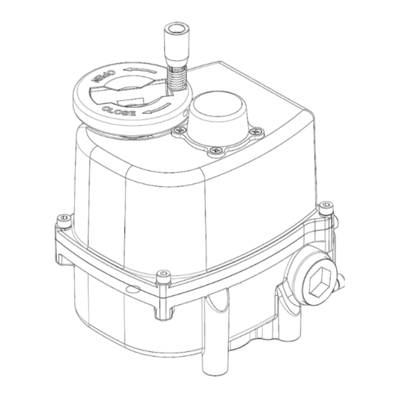
Page 4: Structure Of Actuator
Base body Chamber of Cable entry terminal block Bottom flange F03, F04 & F05 Bottom bore Indicator 14X14 Double square Main P.C.B Motor Limit switch Limit switch cam Manual lever Page 4 CR-TEC Engineering Inc. • info@crtec.com • www.crtec.com • 203-318-9500... -
Page 5: Specifications
F03, F05 & F07 Bottom Bore 14 X 14 Double square (11X11mm available) Operation Time (No Load) 13sec. Indicator Dome type mechanical indicator Travel Angle ±5% 90° Enclosure Weather-proof IP67 Page 5 CR-TEC Engineering Inc. • info@crtec.com • www.crtec.com • 203-318-9500... -
Page 6: Dimensions
5. Dimension Page 6 CR-TEC Engineering Inc. • info@crtec.com • www.crtec.com • 203-318-9500... -
Page 7: Actuator Installation And Set-Up
Mounting is most easily done with the valve shaft pointing vertically upward, but the actuator may be mounted in any position. CR50S actuators are supplied with a female drive output. The bottom bolt pattern is drilled as F03, F05 & F07 according to ISO5211. - Page 8 LINE (L) Free Voltage AC 4 WIRE (ON - OFF) POSITION OUTPUT SWITCHES 24V AC/DC 3 WIRE 24 VAC (L) 24 VDC (-) 24V AC/DC 3 WIRE (ON - OFF) Page 8 CR-TEC Engineering Inc. • info@crtec.com • www.crtec.com • 203-318-9500...
- Page 9 24V AC/DC 4 WIRE (ON - OFF) POSITION OUTPUT FREE VOLTAGE AC INPUT OUTPUT SWITCHES MODULATING SIGNAL SIGNAL Free Voltage AC (Modulating) POSITION OUTPUT 24V AC/DC INPUT OUTPUT SWITCHES MODULATING SIGNAL SIGNAL 24V AC/DC (Modulating) Page 9 CR-TEC Engineering Inc. • info@crtec.com • www.crtec.com • 203-318-9500...
- Page 10 Wiring Diagram - Optional DIN Connector POWER SUPPLY : 3P+T DIN43650 CONNECTOR SUGGESTED CUSTOMER WIRING 3-Position Switch Control (Open/Close) Open Close DIN Wiring for Modulating Option Page 10 CR-TEC Engineering Inc. • info@crtec.com • www.crtec.com • 203-318-9500...
-
Page 11: Limit Switch Setting
Verify the actuator against valve rotation Valve only opens or closes partially with motor Limit switch incorrectly set Over torque : Incorrectly sized actuator Jammed valve Damaged or bent valve stem Page 11 CR-TEC Engineering Inc. • info@crtec.com • www.crtec.com • 203-318-9500... -
Page 12: Maintenance
· Confirm that wiring is insulated, connected and terminated properly. · Check enclosure O-ring seals and verify that the O-ring is not pinched between the flanges. · Visually inspect during open/close cycle. Page 12 CR-TEC Engineering Inc. • info@crtec.com • www.crtec.com • 203-318-9500... -
Page 13: Instruction Of Pcu Card
± 1% Input Position Conversion Accuracy ± 1% Output Position Conversion Accuracy Ambient Temperature -4° F to 140° F (-20° C to +60°C) Ambient Humidity 90% RH Max. (non-condensing) Page 13 CR-TEC Engineering Inc. • info@crtec.com • www.crtec.com • 203-318-9500... -
Page 14: Modulating Set-Up
2. Manual mode DIP S/W “1” is ON. · For open, push “OP” button and push “CL” for close. · ※ Actuator do not respond to input signal during manual mode. Page 14 CR-TEC Engineering Inc. • info@crtec.com • www.crtec.com • 203-318-9500... - Page 15 HUNTING means the actuator doesn’t stop at the right position and repeats open or close to find the right position. HUNTING might be the reason of the motor burning and damages of the potentiometer and PCU card. Page 15 CR-TEC Engineering Inc. • info@crtec.com • www.crtec.com • 203-318-9500...
- Page 16 CR-TEC reserves the right to change or remove products or services from its range at any time and without prior notification or obligation. CR-TEC does not assume any liability for consequences resulting from the use of this document. There is no guarantee that the information provided here is complete, accurate or up to date.
Need help?
Do you have a question about the CR50S and is the answer not in the manual?
Questions and answers