Advertisement
Quick Links
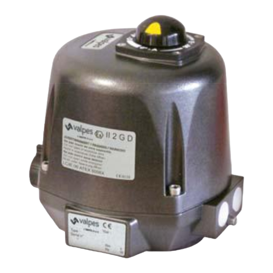
VRX•VSX
Electric Actuators for ATEX Explosive Areas
Installation and Operation Manual
25Nm
IP68
50%
Enclosure protection
Duty cycle
LCIE 06 ATEX 6006 X · II 2 G D Ex db IIB T6 Gb · Ex tb IIIC T80°C Db · T
400 V (R00) :
II 2 G D Ex db IIB T5 Gb · Ex tb IIIC T95°C Db · T
GS6, GPS & GFS : II 2 G D Ex db IIB T6 Gb · Ex tb IIIC T80°C Db · T
IECEx LCIE 21.0015X
ITS21UKEX0157X · n
Battery
Backup
BBPR
Anticondensation
heater
0359
o
3
POSI
POSITIONS
Positioning
= -20 °C à +70 °C
a
= -20 °C à +54 °C
a
= -10 °C à +40 °C
a
Advertisement

Related Manuals for CR-Tec VRX


Summary of Contents for CR-Tec VRX
- Page 1 VRX•VSX Electric Actuators for ATEX Explosive Areas Installation and Operation Manual 25Nm Battery Backup IP68 POSI BBPR POSITIONS Anticondensation Enclosure protection Duty cycle heater Positioning LCIE 06 ATEX 6006 X · II 2 G D Ex db IIB T6 Gb · Ex tb IIIC T80°C Db · T = -20 °C à...
-
Page 2: Table Of Contents
This product meets the European Directive 2012/19/UE about electrical and electronic equipment (DEEE). It mustn't be mixed with common waste. Please, recycle or dispose of them according to your country laws. CR-TEC Engineering Inc. • info@crtec.com • www.crtec.com • 203-318-9500... -
Page 3: Position Indicator
Exploded view VSX models VRX models Part Description Part Description 1 Position indicator 10 Handwheel 2 Cover 11 Housing 3 CHC M6 x 30 A2 stainless steel screws 12 Identification label 4 Motor 13 Auxiliary limit switch terminal 5 Pilot and power supply board... - Page 4 INTRODUCTION This manual has been designed to guide you through the installation and use of the ATEX and IECEx VRX and VSX electric actuators. Read it carefully before using our products and keep it in a safe place. DESCRIPTION The VALVES electric actuators have been designed to allow the piloting of a 1/4 turn valve (or 180° in the case of a 3-position version).
- Page 5 If you are ever uncertain about a particular task or the proper method of operating this equipment, don’t hesitate to contact CR-TEC Engineering Inc. • info@crtec.com • www.crtec.com • 203-318-9500...
- Page 6 Position indicators VRX models Modular position indicator with three removable position markers (3 yellow + 2 black), adjustable ac- cording the type of valve to be actuated. Valve 0° 90° 180° 2-way: 0° = closed 90° = open 3-way (L) :...
-
Page 7: Dimensions
Dimensions VRX models Ø70 ISO F07 4xM8 Square / Star 17mm Drive depth 19mm ISO5211 connection F05 Diameter 50 mm 70 mm Ø50 ISO F05 4xM6 Taraudé M M6 Ø170 Depth 15 mm 17 mm Screw number 4 Screws maximal length... -
Page 8: Mounting On Valve
The priority functioning mode of this actuator is electric. Be sure than the power supply is switched off before using the manual override. VRX models 1. Turn the knob to position MAN (counter-clockwise) and hold it in position. 2. Turn the outgoing drive shaft of the actuator with the help of an adjusting spanner. -
Page 9: Electronic Boards
=> check that the valve torque is not superior to the maximum torque stand by the actuator => check that the actuator do not exceed the duty cycle indicated (possible overheat) To re-start the actuator, reverse the sense of rotation or switch the power off and on. CR-TEC Engineering Inc. • info@crtec.com • www.crtec.com • 203-318-9500... - Page 10 • 4 to 24 V D and 12 to 250 V AC • mi imum current 100 mA • maxim m current 5 A (resistive), 0.5 A (motor), 0.125 A (capacitive loads) CR-TEC Engineering Inc. • info@crtec.com • www.crtec.com • 203-318-9500...
-
Page 11: Standard Models
(FC1) and the black cam is used to detect the closed position (FC2). To adjust the position of the auxiliary contacts, make rotate the two superior cams by using the appropriate wrench. CR-TEC Engineering Inc. - Page 12 Auxiliary limit switch 1 NC Auxiliary limit switch 2 NC POWER SUPPLY AND CONTROL 3-Position Switch Control On-Off Switch Control POSITION OUTPUT SWITCHES Open Open Close 100V-240V 50/60Hz (100V-350V DC) 15V-30V 50/60Hz (12V-48V DC) — CR-TEC Engineering Inc. • info@crtec.com • www.crtec.com • 203-318-9500...
- Page 13 L3 L2 L1 L1 N Ouvert Fermé A B C Ouvert Fermé ERT.B The motor power supply is wired on bistable three-phase relay (not delivered) If working inverted, invert 2 phases of motor CR-TEC Engineering Inc. • info@crtec.com • www.crtec.com • 203-318-9500...
- Page 14 (Type 0-20 or 4-20mA : 5V DC max.) 10 kOhm input impedance if control with voltage (0-10 V) and 100 Ohm input impedance if control with cur- rent (0-20 mA or 4-20 mA) The card resolution is 1° CR-TEC Engineering Inc. • info@crtec.com • www.crtec.com • 203-318-9500...
-
Page 15: Description
Instruction terminal block K3 jumper Feed back terminal block Green and red LEDs Adjustment button MEM Yellow LED : power supply indication Adjustment button CLOSE Potentiometer Adjustment button OPEN Motor connexion K1 jumper CR-TEC Engineering Inc. • info@crtec.com • www.crtec.com • 203-318-9500... - Page 16 Feedback terminal 4-20 mA ou 0-10 V Auxiliary limit switch 2 NF 15,16 Setpoint terminal 4-20 mA ou 0-10 V POWER SUPPLY POSITION OUTPUT SWITCHES 100V-240V 50/60Hz (100V-350V DC) 15V-30V 50/60Hz (12V-48V DC) — SNAA690000 Motor CR-TEC Engineering Inc. • info@crtec.com • www.crtec.com • 203-318-9500...
- Page 17 In the case of an over torque, the motor stops and the 2 LED lights then together to indicate the action of the torque limiter. To re-start it, you must either reverse the sense of rotation, either switch the power off and on. CR-TEC Engineering Inc. • info@crtec.com • www.crtec.com • 203-318-9500...
- Page 18 To adjust the position of the auxiliary contacts, make rotate the 3 superior cams by using the appropriate wrench. Terminals 6 & 9 4 & 8 F4 & F9 0° Closed Open Closed inter Open Open Open 180° Open Closed Fermé CR-TEC Engineering Inc. • info@crtec.com • www.crtec.com • 203-318-9500...
-
Page 19: Description
Failure report Terminal (24V DC / 3A max) F4,F9 Auxiliary limit switch 3 NC N / - Ph / + POSITION OUTPUT SWITCHES 15V-30V 50/60Hz (12V-48V DC) 100V-240V 50/60Hz (100V-350V DC) — SNAA710000 CR-TEC Engineering Inc. • info@crtec.com • www.crtec.com • 203-318-9500... -
Page 20: Bbpr (Gs6) Models
Following a power failure, the BBPR unit will reset after 4 minutes II 2 G D Ex db IIB T6 Gb Ex tb IIIC T80 °C Db LCIE 06 ATEX 6006X / IECEx 21.0015X Ambient temperature: -10 °C to +40 °C CR-TEC Engineering Inc. • info@crtec.com • www.crtec.com • 203-318-9500... - Page 21 For any further information, refer to the operation manual with the reference DSBA3304. CR-TEC Engineering Inc. • info@crtec.com • www.crtec.com • 203-318-9500...
- Page 22 20 V - 30 V 50/60 Hz (20 V - 48 V DC) Charged battery : contact closed F+ : red wire F- : black/white wire T+ : white wire SNBA140000 Battery SNAA690000 CR-TEC Engineering Inc. • info@crtec.com • www.crtec.com • 203-318-9500...
- Page 23 Slow blinking (1 s) : charged battery HORO Weekly scheduler functioning mode Rapid blinking (0.5 s) : battery charging APPR Learning mode selected APPR1 Open position stored (confirmation) POSI Positioning mode APPR2 Closed position stored (confirmation) CR-TEC Engineering Inc. • info@crtec.com • www.crtec.com • 203-318-9500...
- Page 24 . Following a power failure, the BBPR unit will reset after 4 minutes. CR-TEC Engineering Inc. • info@crtec.com • www.crtec.com • 203-318-9500...
- Page 25 0-20 or 4-20mA : 5V DC max.) 10 kOhm input impedance if control with voltage (0-10 V) and 100 Ohm input impedance if control with current (0-20 mA or 4-20 mA) The card resolution is 1° CR-TEC Engineering Inc. • info@crtec.com • www.crtec.com • 203-318-9500...
- Page 26 The battery charge cycle is automatically managed by the electronic card since the first power up. A CTN in the battery pack and a fuse on the electronic card are present to ensure safety in the event of a short circuit or excessively high temperature in the actuator . CR-TEC Engineering Inc. • info@crtec.com • www.crtec.com • 203-318-9500...
- Page 27 Auxiliary limit switch 2 NO D3/D4 F4,F9 Auxiliary limit switch 3 NC 65,66 Charging status feedback terminal A,0,B RS485 connection terminal Following a power failure, the BBPR unit will reset after 4 minutes CR-TEC Engineering Inc. • info@crtec.com • www.crtec.com • 203-318-9500...
- Page 28 10 W The actuator tolerates voltage fluctuation of the electrical grid up to ± 10 % of its nominal system operating voltage The actuator tolerates temporary overvoltages of the electrical grid. CR-TEC Engineering Inc. • info@crtec.com • www.crtec.com • 203-318-9500...
- Page 29 10 W The actuator tolerates voltage fluctuation of the electrical grid up to ± 10 % of its nominal system operating voltage The actuator tolerates temporary overvoltages of the electrical grid. CR-TEC Engineering Inc. • info@crtec.com • www.crtec.com • 203-318-9500...
- Page 30 CR-TEC Engineering Inc. CR-TEC Engineering Inc. 15 Orchard Park Road, Unit 18 Telephone 203-318-9500 • Fax 203-245-2575 Catalog DSBA3401 • Rev. 11/09/2022 info@crtec.com • www.crtec.com...
Need help?
Do you have a question about the VRX and is the answer not in the manual?
Questions and answers