
Related Manuals for IFM ecomat100 O2M102


Summary of Contents for IFM ecomat100 O2M102
- Page 1 Gerätehandbuch Ethernet Kamera für den mobilen Einsatz Device manual Ethernet camera for mobile applications O2M102...
-
Page 2: Table Of Contents
O2M1 ETHERNET CAMERA Contents Safety instructions page 3 Functions and features page 4 2.1 Features at a glance page 4 Mounting 3.1 Mounting accessories page 5 3.2 Mounting dimensions page 5 3.3 Mounting location page 6 Electrical connection 4.1 Ethernet camera page 7 4.1.1 Ethernet connection page 7... -
Page 3: Safety Instructions
The connection terminals may only be supplied with the signals indicated in the technical data and/or on the device label and only the approved accessories of ifm electronic gmbh may be connected. In case of malfunctions or uncertainties please contact the manufacturer. Tamper- ing with the device can lead to serious risks for the safety of persons and plant. -
Page 4: Functions And Features
O2M1 ETHERNET CAMERA 2 Functions and features The Ethernet camera serves for monitoring of areas outside of the field of view in mobile vehicles and utility vehicles. Connection, control and visualisation of the images is carried out via the process and dialogue module PDM360 with colour display. -
Page 5: Mounting
Shaft, straight Ø 12 mm E20938 Mounting example You can find more information about the available accessories at: ➔ Data sheet direct ➔ e.g. O2M102 ➔ Accessories www.ifm.com or directly ➔ Data sheet direct ➔ e.g. E2D110 www.ifm.com 3.2 Mounting dimensions Mounting is done using two M 4 x L screws. -
Page 6: Mounting Location
O2M1 ETHERNET CAMERA Mounting location Mount the camera in front of or above the area to be monitored. The size of the area to be monitored depends on the operating distance: Ethernet Kamera Ethernet camera x 1,3 x 1.3 x 2,6 x 2.6 x 3,9 x 3.9... -
Page 7: Electrical Connection
(4-pole, D-coded) Wiring For information about available connectors please go to: ➔ Data sheet direct➔ e.g. O2M102 ➔ Accessories www.ifm-electronic.com The supply voltage is electrically separated from the housing. 4.1.1 Ethernet connection Use a shielded CAT5 cable. (STP, Shielded Twisted Pair, according to EIA/TIA-568). Max. length 100 m Use screened connector housings. -
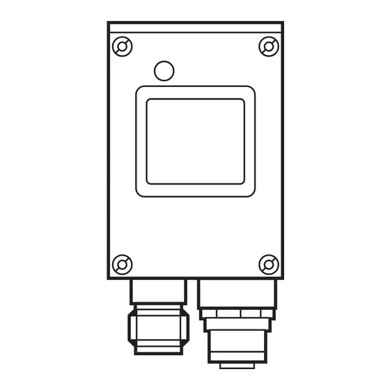
Page 8: Pdm360
O2M1 ETHERNET CAMERA 4.2 PDM360 PDM360 rear view and side view M23 round connector Potential GND (Power) GND (Power) VBB + (Supply) CAN 1 Low CAN 1 High n.c. 2nd RS 232, RxD 2nd RS 232, TxD VBB + (supply switched) GND (Power) GND (Power) Operating connection... -
Page 9: Pc/Notebook
O2M1 ETHERNET CAMERA 4.3 PC/notebook Connection to a PC or to a notebook may be necessary for service purposes (e.g. setting of the IP address). The configuration of the PC Ethernet interface corresponds to that of the service interface (B) of the PDM360. RJ45 Potential TxD +... -
Page 10: Connection Principle Without Hub/Switch
= crossover cable = for the direct connection of network participants Connection principle without hub/switch Crosslink cable (example): art. no. Ethernet connection cable, 2m M12 connector (4-pole, D-coded) – RJ45 (8-pole) E11898 For further information about the connector go to: ➔ Data sheet direct ➔ E11898 www.ifm.com... -
Page 11: Connection Principle With Hub/Switch
O2M1 ETHERNET CAMERA 4.5 Connection principle with hub/switch ■ Several cameras at one PDM360 PDM360 Ethernet Cameras Hub / Switch patch cable (1:1) patch cables (1:1) patch cable (1:1) Patch cable principle (1:1) TxD + TxD + TxD – TxD – Definition patch cable: RxD + RxD +... -
Page 12: Operating And Display Elements
O2M1 ETHERNET CAMERA 5 Operation display Description supply voltage ok green camera ready for operation no supply voltage power supply interrupted Operating indication O2M1xx... -
Page 13: Set-Up
O2M1 ETHERNET CAMERA 6 Set-up 6.1 IP addresses factory setting PDM360 PC / Notebook Ethernet Camera 192.168.82.247 192.168.82.248 192.168.82.15 PC/notebook only for parameter setting Hub / Switch patch cable (1:1) patch cables (1:1) Example 1: IP address allocation The address ranges of all network participants must be identical. This range of the IP address is also called Net ID. -
Page 14: Ip Address Allocation Cameras
The online description of the functions, operation and device-specific libraries of the PDM360 family is part of the CoDeSys online help. It is also available for download on the internet. ➔ Data sheet direct ➔ e.g. O2M102 ➔ Download/Software www.ifm.com 6.1.2 IP address allocation cameras 192.168.82.18 192.168.82.247... - Page 15 O2M1 ETHERNET CAMERA 6. Click on “Change IP address”. Start window “O2M1xx WebConfig” 7. Enter the new address in the field “IP address” and click on “Submit” to send it to the camera. O2M1xx IP configuration...
- Page 16 O2M1 ETHERNET CAMERA A confirmation appears if the address was successfully written to the flash mem- ory of the camera. Confirmation of the address change Error message in case of invalid IP address (e.g. wrong address range)
- Page 17 O2M1 ETHERNET CAMERA An inadvertent, wrong address allocation makes subsequent communica- tion with the camera impossible. For this reason, the following final test must be carried out. 8. Click on “Reboot”. 9. Enter the new IP address of the camera in the address line of the browser and confirm with “Enter”...
-
Page 18: Parameter Setting Pdm360
PDM360 (art. no. CR1051) and the camera. After installation of the CD, the library will be stored in the directory: ...\ ifm electronic \ CoDeSys V2.3 \ Targets \ ifm \ Library \ ifm_CR1051 The library uses functions of the library “ifm_Camera_Vxxxxxx”. It is loaded auto- matically.”ifm_Camera_Vxxxxxx”... -
Page 19: Parameter Overview
O2M1 ETHERNET CAMERA 6.2.3 Parameter overview Name Data type Description Inputs C_ENABLE BOOL camera ON/OFF TRUE: initialisation of the function, transmission of image data Note: If TRUE, the PDM360 visualisation is not refreshed C_ADDR STRING (15) IP address camera, factory setting: 192.168.82.15 C_ROTATION WORD rotate image clockwise (values: 90/180/270) - Page 20 O2M1 ETHERNET CAMERA Name Data type Description Outputs C_RESULT BYTE function not initialised or not active function successfully initialised parameters successfully written function being processed error; connection disturbed or interrupted parameter not written reinitialise function 97: check last byte of IP dress last byte of the IP adress between camera and PDM has to be different 98: PDM IP adress and camera IP adress...
-
Page 21: Mode Combinations (1
O2M1 ETHERNET CAMERA 6.2.4 MODE combinations (1...4 cameras) Full screen 1 camera active, no visualisation C_MODE = 1 C_WINDOW_HEIGHT = not defined Part screen 1 camera active, visualisation up to 120 px at the bottom C_MODE = 2 C_WINDOW_HEIGHT = 120...240 px (height camera image) ¼... - Page 22 O2M1 ETHERNET CAMERA ¼ screen at the top left / bottom left / bottom right 3 cameras active, no visualisation Camera 1: C_MODE = 30, at the top left Camera 2: C_MODE = 50, at the bottom left Camera 3: C_MODE = 60, at the bottom right C_WINDOW_HEIGHT = not defined (all cameras) ¼...
-
Page 23: Technical Data
O2M1 ETHERNET CAMERA 7 Technical data 7.1 O2M102 O2M102 Ethernet camera Angle of aperture 80° Lens heating M12 x1 22,2 M12x1 35,5 46,5 1) Centre of the lens axes Electrical design Operating distance Field of view size 2 x 1.3 4 x 2.6 10 x 6.6 Operating voltage... -
Page 24: Maintenance, Repair And Disposal
Dispose of the device in accordance with the national environmental regulations. 9 Approvals/standards Test standards and provisions → 7 Technical data. The CE Declaration of Conformity and the e1 approval are available at: ➔ Data sheet direct ➔ e.g. O2M102 ➔ Approvals www.ifm.com...
Need help?
Do you have a question about the ecomat100 O2M102 and is the answer not in the manual?
Questions and answers