Sign In
Upload
Download
Table of Contents
Contents
Add to my manuals
Delete from my manuals
Share
URL of this page:
HTML Link:
Bookmark this page
Add
Manual will be automatically added to "My Manuals"
Print this page
×
Bookmark added
×
Added to my manuals
Manuals
Brands
IFM Manuals
Digital Camera
O2M20 Series
Operating instructions manual
IFM O2M20 Series Operating Instructions Manual
Robust camera system with analogue video output
Hide thumbs
1
Table Of Contents
2
3
4
5
6
7
8
9
10
11
12
13
14
15
16
17
18
page
of
18
Go
/
18
Contents
Table of Contents
Bookmarks
Table of Contents
Table of Contents
Preliminary Note
1�1 Symbols Used
1�2 Copyright and Trademarks
Safety Instructions
Functions and Features
3�1 Properties
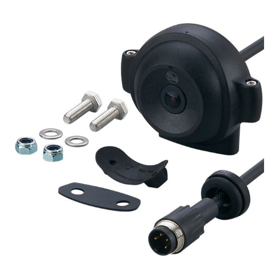
Items Supplied
Accessories
Installation
6�1 Mounting Dimensions
6�2 Mounting and Adjustment of the Device
6�3 Installation Location
Electrical Connection
7�1 Device Wiring
7�2 Device Function at Different Voltages
7�3 Connection with a Dialogue Module
7�4 Connection with a Monitor
7�4�1 Connection of 1 Camera with a Monitor
7�4�2 Connection of 2 Cameras with a Monitor
7�4�3 Connection of 3 Cameras with a Monitor
7�4�4 Connection of 4 Cameras with a Monitor
7�5 Interference Due to External Influences
Maintenance, Repair and Disposal
Approvals/Standards
Advertisement
Quick Links
Download this manual
Operating instructions
Robust camera system with
analogue video output
UK
O2M20x
O2M21x
Table of
Contents
Previous
Page
Next
Page
1
2
3
4
5
Advertisement
Table of Contents
Need help?
Do you have a question about the O2M20 Series and is the answer not in the manual?
Ask a question
Questions and answers
Related Manuals for IFM O2M20 Series
Digital Camera IFM O3D3 Series Brief Instructions
3d camera (9 pages)
Digital Camera IFM M03933 Operating Instructions Manual
2d/3d camera head (14 pages)
Digital Camera IFM O2M200 Operating Instructions Manual
Robust camera system with analogue video output (18 pages)
Digital Camera IFM O2M202 Operating Instructions Manual
Robust camera system with analogue video output (18 pages)
Digital Camera IFM O2M203 Operating Instructions Manual
Robust camera system with analogue video output (18 pages)
Digital Camera IFM Efector 250 O2M110 Device Manual
Ethernet camera for mobile applications (25 pages)
Digital Camera IFM efector 360 O3D301 Brief Instructions
3d camera (9 pages)
Digital Camera IFM Efector 250 O3D301 Brief Instructions
3d camera (9 pages)
Digital Camera IFM Efector 250 O2M113 Device Manual
Ethernet camera for mobile applications (19 pages)
This manual is also suitable for:
O2m21 series
O2m200
O2m201
O2m202
O2m203
O2m210
...
Show all
O2m211
Table of Contents
Print
Rename the bookmark
Delete bookmark?
Delete from my manuals?
Login
Sign In
OR
Sign in with Facebook
Sign in with Google
Upload manual
Upload from disk
Upload from URL


Need help?
Do you have a question about the O2M20 Series and is the answer not in the manual?
Questions and answers