Table of Contents
Advertisement
Quick Links
DEMO CIRCUIT DC1464 QUICK START GUIDE FOR LTC6412
DESCRIPTION
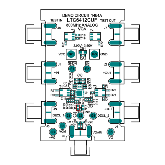
Demonstration circuit 1464 features the LTC6412 ana-
log-controlled VGA. The demo board incorporates a va-
riety of passive components to allow for direct connec-
tion to a 2-port network analyzer or other single-ended
50Ω test system for simplified evaluation.
The 1464 demo board factory default configuration is set
for –V
control mode in the power-on and amplifier-
G
enabled state (SHDN=1, EN=0).
QUICK START PROCEDURE
Demonstration circuit 1464 is easy to set up to evaluate
the performance of the LTC6412. Refer to Figure 1 for
proper measurement equipment setup and follow the
procedure below:
1. Connect SMA cables to the +IN and +OUT ports.
Applied signal should be less than +10dBm peak RF
power to avoid damage in the power-off state.
2. Apply +3.3V between +V
supply current to approximately 150mA.
3. Apply the desired control signal to either the –V
turret or the –V
LTC6412. For this –V
control signal voltage produces a
fier gain.
Arrow.com.
Downloaded from
and GND turrets. Limit
CC
SMA to access the –V
G
G
increase in
control mode, an
G
decrease in ampli-
Analog-Controlled VGA
The demo board is easily configured to access the +V
control mode and EN/SHDN features. Other simple PCB
modifications can accommodate differential input/output
signals and shunt tuning elements for bread-boarding
into larger systems.
Design files for this circuit board are available. Call
the LTC factory.
L
, LTC, LTM, and LT are trademarks of Linear Technology Corporation. Other product
names may be trademarks of the companies that manufacture the products.
This procedure contains only one critical sequence order.
The user must apply supply voltage before applying the
control signal voltage and remove or turn-down the con-
trol signal voltage before turning down the supply volt-
age. This proper sequence will prevent excessive current
through the ESD diodes from the ±V
supply, V
.
CC
Table 1 shows the function of each SMA connector on
the board. Only J1 and J2 are used in the default evalua-
G
tion configuration. Other connectors provide flexibility
pin of the
for fast control signals, differential input/output signals,
and balun loss calibration.
DEMO CIRCUIT 1464
QUICK START GUIDE
800MHz, 31dB Range
pins to the positive
G
LTC6412
G
1
Advertisement
Table of Contents

Related Manuals for Linear Technology DC1464A


Summary of Contents for Linear Technology DC1464A
- Page 1 LTC factory. enabled state (SHDN=1, EN=0). , LTC, LTM, and LT are trademarks of Linear Technology Corporation. Other product names may be trademarks of the companies that manufacture the products. QUICK START PROCEDURE Demonstration circuit 1464 is easy to set up to evaluate the performance of the LTC6412.
- Page 2 DEMO CIRCUIT DC1464 QUICK START GUIDE FOR LTC6412 Table 1. DC1464 SMA Connector Descriptions CONNECTOR FUNCTION Differential input connected to input balun for single-ended operation. J1 (+IN) Drive from a 50 Ohm signal source. No external termination needed. Differential output connected to output balun for single-ended operation. J2 (+OUT) Impedance matched to 50 Ohms for direct connection to a 50 Ohm network/spectrum analyzer input.
- Page 3 DEMO CIRCUIT DC1464 QUICK START GUIDE FOR LTC6412 ADDITIONAL INFORMATION DIFFERENTIAL OUTPUTS SHUTDOWN AND ENABLE The output connectors can be configured for differential The factory default configuration is set for the power-on drive. Move capacitor C21 to location C9 to enable dif- and amplifier-enabled state (SHDN=1, EN=0).
- Page 4 DEMO CIRCUIT DC1464 QUICK START GUIDE FOR LTC6412 Figure 2. DC1464A Schematic Arrow.com. Arrow.com. Arrow.com. Arrow.com. Downloaded from Downloaded from Downloaded from Downloaded from...
- Page 5 DEMO CIRCUIT DC1464 QUICK START GUIDE FOR LTC6412 Table 2. DC1464A Parts List Arrow.com. Arrow.com. Arrow.com. Arrow.com. Arrow.com. Downloaded from Downloaded from Downloaded from Downloaded from Downloaded from...
Need help?
Do you have a question about the DC1464A and is the answer not in the manual?
Questions and answers