Advertisement
DESCRIPTION
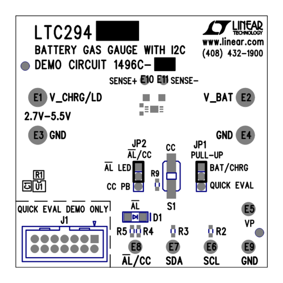
Demonstration circuit 1496C-A (Figure 1) features the
LTC
2941. Demonstration circuit 1496C-B features the
®
LTC2942. Demonstration circuit 1496C-C features the
LTC2941-1. Demonstration circuit 1496C-D features the
LTC2942-1. The C, D options have parts that use an internal
sense resistor while the A, B options rely on an external
precision sense resistor. All four devices measure battery
charge state in handheld PC and portable product applica-
tions. The operating range is perfectly suited for single
cell Li-Ion batteries. A precision analog coulomb counter
integrates current through a sense resistor between the
battery's positive terminal and the load or charger. The
LTC2942 adds battery voltage and on-chip temperature
measurement with an internal 14-bit No Latency ∆Σ™
ADC. The three measured quantities (charge, voltage and
temperature) are stored in internal registers accessible via
the onboard SMBus/I
The LTC2941/LTC2941-1 has programmable high and
low thresholds for accumulated charge. The LTC2942/
LTC2942-1 has programmable high and low thresholds for
all three measured quantities. If a programmed threshold
Arrow.com.
Downloaded from
2
C interface.
DEMO MANUAL DC1496C
Battery Gas Gauge with I
Interface and 14-Bit ADC
is exceeded, the device reports an alert using either the
SMBus alert protocol or by setting a flag in the internal
status register.
The LTC2941 and LTC2942 require only a single low
value sense resistor to set the measured current range.
The LTC2941-1 and the LTC2942-1 have their own 50mΩ
internal resistor. The default value assembled on the
DC1496 is 100mΩ for a maximum current measurement
of 500mA. Both parts have a software-configurable charge
complete/alert pin. When the pin is set for charge com-
plete, a jumper connects the pushbutton which simulates
a logic high input to indicate a full battery. When the pin is
configured for alert, the same jumper is used to connect
a red LED that indicates an alert is present.
The DC1496C is a part of the QuikEval™ system for quick
evaluation with a host controller through a PC.
Design files for this circuit board are available at
http://www.linear.com/demo/DC1496C.
L, LT, LTC, LTM, Linear Technology and the Linear logo are registered trademarks and
No Latency ∆Σ and QuikEval are trademarks of Linear Technology Corporation. All other
trademarks are the property of their respective owners.
Figure 1. DC1496C
LTC2941/LTC2942:
2
C
dc1496cfb
1
Advertisement
Table of Contents

Related Manuals for Linear Technology DC1496C


Summary of Contents for Linear Technology DC1496C
- Page 1 The LTC2942/ LTC2942-1 has programmable high and low thresholds for L, LT, LTC, LTM, Linear Technology and the Linear logo are registered trademarks and No Latency ∆Σ and QuikEval are trademarks of Linear Technology Corporation. All other all three measured quantities.
-
Page 2: Quick Start Procedure
Use SENSE and SENSE test points to read voltage across the sense resistor. SENSE BATTERY CHARGER LOAD 1-CELL – Li-Ion – BUS PULL-UP VOLTAGE TO QuikEval TO MICROCONTROLLER Figure 2. DC1496C Basic Setup dc1496cfb Arrow.com. Arrow.com. Downloaded from Downloaded from... - Page 3 DEMO MANUAL DC1496C QuikEval INTERFACE The DC1496C can be connected to a DC590 and used LTC2941 and LTC2942 Display with the QuikEval software. The DC590 connects to a PC On a refresh or poll, the software reads Status bit A[7] to through USB.
- Page 4 Analog portion of the LTC2941/42/41-1/42-1 and set the Enter here the sense resistor value used in the application. device in a low current state. The default for the DC1496C is a 100mΩ sense resistor. Check LTC2941-1/LTC2942-1 if one of these devices is Register Read/Write used in place of the default IC.
- Page 5 DEMO MANUAL DC1496C QuikEval INTERFACE Calculator Tool higher count. Switching back and forth between Hex and Unit can be used as a conversion tool. A calculator tool is available in the tool bar options under Tools. In this calculator (Figure 4), enter the maximum cur-...
-
Page 6: Parts List
DEMO MANUAL DC1496C PARTS LIST ITEM REFERENCE PART DESCRIPTION MANUFACTURE/PART NUMBER C1, C2 CAP., CHIP X7R, 0.1µF, 25V, 0603 AVX, 06033C104KAT2A E1-E4 TURRET, TESTPOINT 0.094" MILL-MAX, 2501-2-00-80-00-00-07-0 E5-E9 TURRET, TESTPOINT 0.064" MILL-MAX, 2308-2-00-80-00-00-07-0 E10, E11 TURRET, TESTPOINT 0.054" MILL-MAX, 2309-1-00-80-00-00-07-0... -
Page 7: Schematic Diagram
DEMO MANUAL DC1496C SCHEMATIC DIAGRAM dc1496cfb Arrow.com. Arrow.com. Arrow.com. Arrow.com. Arrow.com. Arrow.com. Arrow.com. Downloaded from Downloaded from Downloaded from Downloaded from Downloaded from Downloaded from Downloaded from... - Page 8 DEMO MANUAL DC1496C PCB LAYOUT AND FILM Silkscreen Top Component Side Inner Layer 2 dc1496cfb Arrow.com. Arrow.com. Arrow.com. Arrow.com. Arrow.com. Arrow.com. Arrow.com. Arrow.com. Downloaded from Downloaded from Downloaded from Downloaded from Downloaded from Downloaded from Downloaded from Downloaded from...
-
Page 9: Revision History
Information furnished by Linear Technology Corporation is believed to be accurate and reliable. However, no responsibility is assumed for its use. Linear Technology Corporation makes no representa- tion that the interconnection of its circuits as described herein will not infringe on existing patent rights. - Page 10 Linear Technology Corporation (LTC) provides the enclosed product(s) under the following AS IS conditions: This demonstration board (DEMO BOARD) kit being sold or provided by Linear Technology is intended for use for ENGINEERING DEVELOPMENT OR EVALUATION PURPOSES ONLY and is not provided by LTC for commercial use. As such, the DEMO BOARD herein may not be complete in terms of required design-, marketing-, and/or manufacturing-related protective considerations, including but not limited to product safety measures typically found in finished commercial goods.
Need help?
Do you have a question about the DC1496C and is the answer not in the manual?
Questions and answers