Advertisement
Quick Links
DESCRIPTION
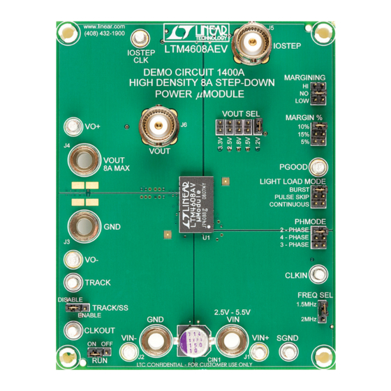
Demonstration circuit DC1400A features the LTM
the high effi ciency, high density switch mode step-down
power module. The input voltage range is 2.5V to 5.5V.
The output voltage is jumper selectable from 0.6V to 3.3V.
The rated load current is 8A although derating is necessary
for certain V
, V
and thermal conditions. LTM4608A
IN
OUT
offers a novel phase-shift clock output to support current
sharing with other regulators. The TRACK/SS pin allows
the user to program output voltage ramp-up and ramp-
down slew rate. The same pin also allows the output to
PERFORMANCE SUMMARY
PARAMETER
Input Voltage Range
Output Voltage Range
Maximum Continuous Output Current
Default Operating Frequency
Effi ciency
BOARD PHOTO
DEMO MANUAL DC1400A
coincidentally or ratiometrically track another voltage
4608AEV,
®
rail. The margining function is provided for users who
wish to stress their systems by varying supply voltages
during testing. The LTM4608A data sheet must be read in
conjunction with this demo manual prior to working on
or modifying the DC1400A
Design fi les for this circuit board are available at
http://www.linear.com/demo
L, LT, LTC, LTM, μModule, Linear Technology and the Linear logo are registered trademarks of
Linear Technology Corporation. All other trademarks are the property of their respective owners.
(T
= 25°C)
A
CONDITION
Jumper Selectable (Open for 0.6V)
Derating is Necessary for Certain V
Thermal Conditions
V
= 5V, V
= 2.5V, I
= 8A
IN
OUT
OUT
LTM4608AEV:
8A Step-Down Power
µModule
VALUE
2.5V to 5.5V
1.2V, 1.5V, 1.8V, 2.5V, 3.3V; ±2%
, V
and
8A DC
IN
OUT
1.5MHz
84.5%, See Figure 3 for More Information
Regulator
®
dc1400af
1
Advertisement

Related Manuals for Linear Technology DC1400A


Summary of Contents for Linear Technology DC1400A
- Page 1 L, LT, LTC, LTM, μModule, Linear Technology and the Linear logo are registered trademarks of down slew rate. The same pin also allows the output to Linear Technology Corporation. All other trademarks are the property of their respective owners.
-
Page 2: Quick Start Procedure
DEMO MANUAL DC1400A QUICK START PROCEDURE Demonstration circuit DC1400A is an easy way to evalu- 5. To measure the input and output ripple, please refer to ate the LTM4608AEV. Please refer to Figure 1 for proper Figure 2 for proper setup. - Page 3 DEMO MANUAL DC1400A QUICK START PROCEDURE Effi ciency vs Load Current with 5V , 1.2V Effi ciency vs Load Current with 5V , 1.5V BURST BURST PULSE SKIPPING PULSE SKIPPING CONTINUOUS CONTINUOUS LOAD CURRENT (A) LOAD CURRENT (A) DC1400 F03a DC1400 F03b Effi...
- Page 4 DEMO MANUAL DC1400A PARTS LIST ITEM REFERENCE DESCRIPTION MANUFACTURER’S PART NUMBER Required Circuit Components CAP , 0603 47pF 10% 25V NPO AVX 06033A470KAT CIN1 CAP , 150μF 20% 10V ELEC SANYO 10SVPA150MAA CIN5, CIN4 CAP , 0805 10μF 10% 6.3V X5R AVX 08056D106KAT2A CAP , 1206 22μF 20% 6.3V X5R...
-
Page 5: Schematic Diagram
Information furnished by Linear Technology Corporation is believed to be accurate and reliable. However, no responsibility is assumed for its use. Linear Technology Corporation makes no representation that the interconnection of its circuits as described herein will not infringe on existing patent rights. - Page 6 Linear Technology Corporation (LTC) provides the enclosed product(s) under the following AS IS conditions: This demonstration board (DEMO BOARD) kit being sold or provided by Linear Technology is intended for use for ENGINEERING DEVELOPMENT OR EVALUATION PURPOSES ONLY and is not provided by LTC for commercial use. As such, the DEMO BOARD herein may not be complete in terms of required design-, marketing-, and/or manufacturing-related protective considerations, including but not limited to product safety measures typically found in finished commercial goods.
Need help?
Do you have a question about the DC1400A and is the answer not in the manual?
Questions and answers