Table of Contents

Related Manuals for Pentair IntelliChlor COMSYS-14


Summary of Contents for Pentair IntelliChlor COMSYS-14
- Page 1 IntelliChlor ® Electronic Chlorine Generator Commercial System COMSYS-14 520976 Installation Guide Patents pending Certified to NSF/ANSI 50 IMPORTANT SAFETY INSTRUCTIONS READ AND FOLLOW ALL INSTRUCTIONS SAVE THESE INSTRUCTIONS...
- Page 2 Pentair Water Pool and Spa, Inc. Those names and brands may be the trademarks or registered trademarks of those parties or others.
-
Page 3: Table Of Contents
Contents IMPORTANT SAFETY PRECAUTIONS ....................... ii Installation Steps Summary ........................iii Technical Support ............................iii ® IntelliChlor Electronic Chlorine Generator COMSYS-14 Overview ....... 1 Features .......................... 1 Preparing the Site ......................1 Mount Power Center Banks To Wall ................2 Installation ........................ -
Page 4: Important Safety Precautions
IMPORTANT SAFETY PRECAUTIONS SAVE THESE INSTRUCTIONS Important Notice: Attention Installer: This manual contains important information about the installation, operation and safe use of this product. This information should be given to the owner and/or operator of this equipment. When installing and using this electrical equipment, basic safety precautions should always be followed, including the following: WARNING: IMPORTANT SAFETY INSTRUCTIONS PERTAINING TO A RISK OF FIRE, ELECTRIC SHOCK, OR INJURY TO PERSONS. - Page 5 CAUTION - Install the IECG a minimum of three (3) feet away from the heater outlet. CAUTION - It is recommended to install a Pentair two (3) inch CHECK VALVE (P/N 263060) between the input side of the IECG and the main heater output pipe.
-
Page 6: Technical Support
Technical Support Sanford, North Carolina (8 A.M. to 5 P.M. Eastern Time) Moorpark, California (8 A.M. to 5 P.M. Pacific Time) Phone: (800) 831-7133 Fax: (800) 284-4151 Web sites visit www.pentairpool.com and www.staritepool.com IntelliChlor Electronic Chlorine Generator COMSYS-14 Installation Guide... -
Page 7: Intellichlor Electronic Chlorine Generator Comsys-14 Overview
IntelliChlor Electronic Chlorine Generator COMSYS-14 Overview The IntelliChlor COMSYS-14 commercial system consists of seven IntelliChlor cells and seven power centers (primary and secondary). Each cell can produce up to 2.00 lbs of pure chlorine per 24 hours of operation. These cells can sanitize either a pool or spa, or combination of both. -
Page 8: Mount Power Center Banks To Wall
Installation Before installing the IntelliChlor CIC60 system, please read all SAFETY PRECAUTIONS below. Kit Contents - Seven Power Centers (one primary, six secondary) - One CIC60P cell - Six CIC60S cells - Installation Guide (this manual) Required Tools - Medium phillips or flathead screwdriver (and twelve screws) - Electric drill and 1/4"... -
Page 9: Connect Ac Power Wires And Orp Sensor Wires
Mount Power Center Banks To Wall (Continued) 4. Remove the cover retaining screw and remove the cover from upper side left PRIMARY power center and the lower left side SECONDARY power center. CPC104 Remove cover screw and cover from PRIMARY POWER CENTER Mount power center bank to wall using six (6) - Page 10 Connect AC Power Wires and ORP Sensor Wires (Continued) 4. Splice the incoming AC power wires onto the two wires labeled WIRED FOR 220V. Do not apply AC power yet. 5. Connect the two (2) twisted wires labeled ORP SENSOR to the ORP chlorine controller panel (AcuTrol, etc).
- Page 11 7. Remove the cover retaining screw and remove the cover from the SECONDARY power center, located on the top bank, far right side. 8. Route the communication cable from the CPC203 power center through the bottom hole of the CPC104 Secondary power center. 9.
-
Page 12: Assemble The Manifold
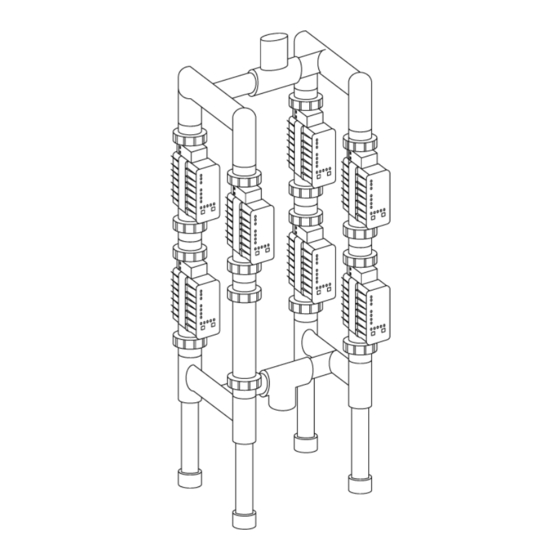
Assemble the Manifold 1. Place an o-ring into groove on union coupling (two per cell). 2. Place each cell on the manifold and tighten coupling nut securely. Be sure the o-ring stays in place. Note: Cells labeled PRIMARY and SECONDARY can be placed anywhere in the manifold, they do not need to be in a specific location. -
Page 13: Connect The Intellichlor Cells
Connect the IntelliChlor Cells 1. Connect the cell power connector, labeled PRIMARY (CIC60P), into the receptacle on the bottom of the power center labeled PRIMARY. While holding the connector on the receptacle, turn it slowly until the plug pins are inserted into the receptacle, then twist the to lock in place. 2. -
Page 14: Power Centers
Power Centers The PRIMARY and SECONDARY power centers are pre-wired as shown below. CPC104 PRIMARY SECONDARY SECONDARY SECONDARY Terminal Screw Connector SECONDARY SECONDARY SECONDARY CPC203 Power Center connection wire Power Centers (Front View) IntelliChlor Electronic Chlorine Generator COMSYS-14 Installation Guide... -
Page 15: Power Up The System
Power Up the system 1. Switch the AC circuit breaker to ON to apply AC power to the system. 2. After the system is powered up for one minute, if any SECONDARY cell shows a red PWR light, the communications to that cell is not connected. Open the power center covers and verify the two green and yellow wires on each terminal block are connected and in the same order. -
Page 16: Troubleshooting
Troubleshooting The IntelliChlor 100% light does not come on when the chlorine controller calls for chlorine 1. Verify the ORP controller is opening and closing the dry-contact output. 2. Remove the ORP SENSOR wires connection from the PRIMARY power center and the ORP controller. - Page 17 The PWR light is red. 1. Communication has been lost between the power centers and cells. Verify the communication connection. See “POWER UP THE SYSTEM” step 3, page 7. 2. If the communications are connected, replace the master board in the PRIMARY power center. The cell is not powered up 1.
- Page 18 Blank Page IntelliChlor Electronic Chlorine Generator COMSYS-14 Installation Guide...
- Page 19 Customer following the procedures set forth below, Pentair Water will, at its option, repair or replace such item or part at its own cost and expense. Pentair Water’s maximum obligation under this warranty is limited to the repair and replacement of the IECG.
- Page 20 Upon receipt of this communication, Pentair Water will promptly notify the Customer of the address to which the defective item may be shipped. The Customer shall then ship the item, freight prepaid, to the address indicated, together with a "RETURN GOODS AUTHORIZATION"...
Need help?
Do you have a question about the IntelliChlor COMSYS-14 and is the answer not in the manual?
Questions and answers