Advertisement
Quick Links
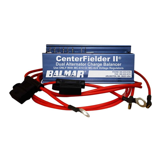
Centerfielder II
CFII-12/24
Introduction
Designed for use in application requiring balanced charge control from
two alternators and two regulators on twin engines, the Centerfielder
II: CFII-12/24 makes it possible to utilize the combined output of both
alternators to supply optimized charging to a single large battery bank.
By monitoring the ignition and field voltages at port and starboard
regulators, the CFII-12/24 determines when both engines are running,
and directs field current from the master (starboard) regulator to both
alternators. By controlling both alternators with the same field source,
the CFII-12/24 ensures that alternators can work together to ensure
optimal charging at a single large battery bank.
Table of Contents
Introduction
Safety Considerations
CFII-12/24 Installation
Unpacking Box
Locate/Mount Regulator
INSTALLATION AND OPERATION MANUAL
1
Regulator Terminal Layout
1
12 Volt Wire Diagram
2
24 Volt Wire Diagram
2
Warranty
2
Safety Considerations
1.
Always disconnect your battery banks and
ensure that switches are "OFF" prior to
installing your regulator.
2.
Remove loose-fitting clothing or jewelry,
which could become entangled in your
motor or other machinery prior to installing
regulator.
3.
Wear ANSI-approved safety eye-wear and
protective gear.
4.
DO NOT attempt to modify the regulator.
Modifications could result in damage to
your charging system, and will void your
warranty.
3-4
5
5.
DO NOT attempt installation if you are tired
6
or fatigued.
7
6.
Ensure that the engine has cooled before
initiating installation.
7.
DO NOT attempt regulator installation while
using alcohol or medication that could
impair your judgment or reaction time.
8.
Always use the right tool for the job.
Improper tool use may damage regulator
or your vessel, and could result in personal
injury.
9.
Take time to read the manual. Equipment
damage and possible injuries may result
from an incomplete understanding of the
installation and operation of the MC-612-
DUAL regulator. If you are unfamiliar with
marine electrical systems, consult with a
licensed marine electrician.
Advertisement

Related Manuals for Balmar Centerfielder II


Summary of Contents for Balmar Centerfielder II
- Page 1 Centerfielder II CFII-12/24 INSTALLATION AND OPERATION MANUAL Introduction Safety Considerations Designed for use in application requiring balanced charge control from two alternators and two regulators on twin engines, the Centerfielder Always disconnect your battery banks and II: CFII-12/24 makes it possible to utilize the combined output of both ensure that switches are “OFF”...
-
Page 2: Unpacking The Box
Installation The Centerfieldr II is easy to install. You will find, included with the Centerfielder II, a collction of wiring terminal connectors as well as two fused 12-gauge RED wires required to replace the standard 14-gauge RED power wires in the Max Charge regulator’... - Page 3 5. PORT REGULATOR IGNITION - Connect Terminal #4 to the port voltage regulator’s BROWN ignition wire. A BROWN 14-Gauge user-supplied wire is recommended. A female 1/4” spade terminal is supplied with the Centerfielder II. 6. PORT IGNITION INPUT - Connect Terminal #5 to the port engine ignition switch or port engine oil pressure switch.
- Page 4 7. PORT REGULATOR DASH LAMP TERMINAL- Connect Terminal #6 to the port voltage regulator’s dash lamp terminal via a user supplied 16-gauge wire. Female 1/4” spade terminals are supplied for connecting to Terminal #6. 8. PORT DASH LAMP TERMINAL- Connect Terminal #7 to the port dash lamp via a user supplied 16-gauge wire. Female 1/4”...
- Page 5 Centerfielder II Installation - 12-Volt System REGULATOR IGNITION WIRE REGULATOR FIELD WIRE HOUSE BATTERY REGULATOR POWER WIRE BANK POSITIVE BATTERY CABLE PORT STBD. VOLTAGE SENSE WIRE IGNITION IGNITION SWITCH SWITCH DASH LAMP WIRE GROUND WIRE POWER POST STARBOARD PORT REGULATOR REGULATOR CENTERFIELDER SLAVE...
- Page 6 Centerfielder II Installation - 24-Volt System REGULATOR IGNITION WIRE REGULATOR FIELD WIRE HOUSE BATTERY REGULATOR POWER WIRE BANK POSITIVE BATTERY CABLE PORT STBD. STATOR WIRE IGNITION IGNITION SWITCH SWITCH DASH LAMP WIRE GROUND WIRE POWER POST PORT STARBOARD MAX CHARGE REGULATOR CENTERFIELDER MASTER...
Need help?
Do you have a question about the Centerfielder II and is the answer not in the manual?
Questions and answers