Table of Contents
Advertisement
Advertisement
Table of Contents

Related Manuals for Balmar SG200


Summary of Contents for Balmar SG200
- Page 1 SG200 BATTERY MONITOR Installation & Operation Manual SUP-0250 REV A.
-
Page 2: Table Of Contents
Adding an additional device to the SmartLink Network Setting up multiple SmartShunts on one bank SG200 Layout and Operation Single Button Operation Real-Time Data Setting up the SG200 for the First Time Initial Accuracy Display History BAT TYPE - Selecting the Battery Chemistry... -
Page 3: Safety Precautions
1. Take time to read the manual. Equipment damage and possible injuries may result from an incomplete understanding of the installation and operation of the SG200 Battery Monitor. If you are unfamiliar with marine electrical systems, consult with a qualified marine electrician. -
Page 4: Installation Overview
SG200 Battery Monitor unit, your system wiring or health. The SG200 is designed to monitor a battery or battery bank which is used in deep cycling applications. It relies on the battery being discharged and then charged to learn the battery’s characteristics. - Page 5 NOTE: If a SG200 is used to monitor a starting-only bank using the cable posts, and not the voltage-only leads, then an accurate state of health may not be determined or maintained. The diagram above shows a typical installation with one house battery bank, and two auxiliary or engine start batteries.
-
Page 6: Introduction
(SoC) is a percentage value, showing what percentage of the battery’s capacity is remaining. The SG200 very accurately calculates the State of Charge, and it does so by incorporating a new feature: State of Health (SoH). State of Health is another percentage value, that compares the design capacity of a battery, or the capacity the battery’s manufacture says it should be when new, with it’s actual... - Page 7 Inaccuracy is introduced that is multiplied with each additional cycle that does not reach full 100% charge. For more information about issues that effect battery health and capacity, read the Appendix entitled “Factors Affecting Battery Life”...
-
Page 8: Installation
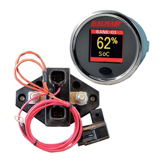
Installation Included in the box The following parts are included in the standard SG200 System Kit. (1) SmartShunt, with 60” fused wire positive wire. (1) Color Display (1) Display mounting bracket and nut (1) 10m SmartLink Cable (1) SmartLink Deutsch-style connector kit, with a connector and wedgelock. - Page 9 The SmartShunt should be located as close to the battery as possible, preferably within 12”. The SG200 uses the SmartShunt to measure current, or how many amperes are going into or out of the battery. Because of this, you must ensure that no loads (like a bilge pump) or sources (like an inverter) are connected directly to the battery.
- Page 10 Installation steps NOTE: The purpose of this manual is to enable the installer to install SG200 in a manner that permits it to operate as designed. This manual is not intended to educate the installer on the regulatory requirements of any particular type of installation.
- Page 11 NOTE: The fuse holder is shipped without the fuse installed, install fuse AFTER completely connecting all of the wires/cables. and all other installation steps. 6. Connect the voltage sense leads to the auxiliary batteries. AUX-1 is a solid orange wire, and AUX-2 is orange/black. Each AUX lead needs to be fused within 6”...
-
Page 12: Adding An Additional Device To The Smartlink Network
Installing the Deutsch-style connector The receptacles for the connector come pre-terminated onto each wire. They must be installed into the connector as shown below. 1. Slide the heat shrink tubing over the bare wires. 2. Slowly push the receptacle into the appropriate hole, until a clicking sound is heard. - Page 13 3. Virtually connect the two SmartShunts together on the SmartLink Network so that they are considered one “Master” SmartShunt by the system. This is accomplished with the SG200 Smartphone App. NOTE: DO NOT connect the shunts in series, one after the other.
-
Page 14: Sg200 Layout And Operation
The SG200 has three main data display areas, as shown below. Single Button Operation The SG200 has a single button for ease of operation. A button press can be: 1. Short Press 2. Long Press (release as soon as screen flashes) 3. -
Page 15: Real-Time Data
SmartShunt will allow you to view the data from that SmartShunt and battery-bank. You will see the SmartShunt bank selected on the top bar of the SG200 screen. Here are some notes concerning the Real-Time Data parameters:... -
Page 16: Setting Up The Sg200 For The First Time
Setting up the SG200 for the First Time When the SG200 Display is first powered up, a splash screen is shown. Pressing the button once will take you to either a screen where you can select the device to be monitored (If two SmartShunts are installed, for instance), or directly to the Real-Time Data if the only devices on the network are a single Display and a single SmartShunt. -
Page 17: Initial Accuracy
Initial Accuracy The SG200 is a self learning product. It continuously monitors the battery bank, and self adjusts over time to improve the accuracy of the two most important parameters, State of Health (SoH) and State of Charge (SoC). On new battery systems, both the State of Health and the State of Charge values may be very close to accurate after the first full charge and a brief relaxation period. -
Page 18: History
History The HISTORY sub-menu shows the following MENU OPTION DESCRIPTION VIEW HISTORY Displays minimum and maximum values for the following parameters: Voltage, Current, SoC, SoH, Power (Watts) VIEW FAULTS Displays details on all faults recorded on the device. CLR HISTORY Reset the min-max values in HISTORY to the current values of those parameters. -
Page 19: Bat Type - Selecting The Battery Chemistry
The default is FLOODLA (see the chemistry table). If this is your chemistry and the installation is new, you may either re-select the chemistry, ensuring that the SG200 is starting fresh, or exit back to MENU and move to the next step. -
Page 20: Capacity - Selecting A Battery Design Capacity
NOTE: Every time a chemistry is selected, all learning is lost, even if you re-select the currently used chemistry. This will mean that the SG200 will need a few charge cycles to obtain peak accuracy. NOTE: If you are uncertain which battery chemistry to select, please contact Balmar Customer Support: http://www.balmar. -
Page 21: Charging - Charge Termination And Charge Efficiency
CHARGING - Charge Termination and Charge Efficiency The CHARGE VOLTAGE and TAPER CURRENT are used together by the SG200 to determine when charge termination has occurred. This is indicated on the Display when a “+” sign shows on the SoC Display. - Page 22 SG200 setting the SoC to 100% and the actual end of charge current. If these values are not correct (CHARGE VOLTAGE too high, or TAPER CURRENT too low, or both) then the SG200 may not be able to properly update the State of Health.
-
Page 23: Advanced Settings
Advanced Settings The advanced menu for any SmartShunt allows the user to perform several levels of reset of SmartLInk devices on the network. An explanation of each of options is in the table below: Menu Option Description RESTART DEV RESTART DEVICE - Reboots the device (a Display or SmartShunt) that is currently selected (Shown at the top of the screen). -
Page 24: Faults And Alerts
Faults and Alerts Alerts Alerts are used to notify the user when a particular threshold on a parameter is passed. For instance, an alert can be set for when the State of Charge ex- ceeds 90%, but also when it drops below 50%. High and low values can be set for most parameters. -
Page 25: Faults
To set an alert, ensure you have the correct SmartShunt selected (the device name shows on the top bar) and select ALERTS from the CONFIG menu. First, select the type of alert you wish to configure, then if you wish to configure for a high or low value. -
Page 26: Comparing Faults And Alerts
The values used to trigger Faults are contained in the Appendix named Fault Thresholds Fault History is accessed from within the History Sub-menu, see History. NOTE: The High Voltage Fault threshold for flooded batteries may be higher than a safe voltage for operating electronics and other equipment. This is to allow for the equalization of batteries without triggering a Fault. -
Page 27: Specifications
Specifications Standard Configuration 1 Bank per SmartShunt Device 2 Start/Auxiliary Voltage Sense Lines (Up to 32 Devices including Dis- plays and SmartShunts can be added to single network.) Supply Voltage Range 8-60V MAX Bank Current-Monitored 1Ah-1310Ah Battery Size Average Supply Current Display On: 20mA @ 12V Sleep Mode: 10mA @ 12V SmartShunt Operating... -
Page 28: Part Numbers
65V. Please remove the fuse on the SmartShunt power lead. NOTE: The SG200 should not be used on 48V systems that are operated in extreme cold environments. In this case, a temperature-compensated charger may use voltages over the safe operating voltage of the SG200. -
Page 29: Fault Thresholds
Fault Thresholds FAULT Flooded TPPL CARFOAM LIFEPO4 Dual Purpose High 16.3 14.3 14.4 Voltage 10.5 10.5 10.5 10.5 10.5 10.5 Voltage High 351A (Scales with multiple SmartShunts in Parallel) Current Converting Reserve Capacity to Amp Hours The following formula converts Reserve capacity, typically expressed in min- utes drawing a 25 amp load, to Amp hours at the 20/HR rate. -
Page 30: Factors Affecting Battery Life
As batteries age, their overall health diminishes. The biggest sign that a battery’s health has declined is seen as reduced capacity. Without the SG200, the easiest way to see if this is happening is to monitor the time it takes a battery to charge using the same charging source. -
Page 31: Cycle Life
Cycle Life Batteries are rated to show how many charge/discharge cycles they are able to endure before their health falls to a point where replacement is necessary. This is typically expressed as XX # of cycles to XX% discharge. It means that if you discharge to a lower value each time before re-charging, the total times this is done is lower than if the battery is only discharged a smaller amount each time. -
Page 32: Balmar Warranty
Components with a manufacturing date greater than ten (10) years old are not covered under the Balmar Warranty, event if the purchase date has been within the past two (2) years. Purchases from unauthorized resellers, which may include some online entities, may not guarantee the purchaser will receive a newly manufactured component, and therefore does not guaranty Warranty coverage. - Page 33 Once Balmar receives the product, we will test the product to determine if the problem is due to a defect in the product. If, at the sole discretion of Balmar, the problem is determined to be a manufacturer defect, Balmar will repair the product or send a new product to replace the defective product.
- Page 34 NOTES...
- Page 35 NOTES...
Need help?
Do you have a question about the SG200 and is the answer not in the manual?
Questions and answers