Chapters
Table of Contents

Related Manuals for Meyer E-58H


Summary of Contents for Meyer E-58H
- Page 1 FORM NO. 1-822R1 May 2011 E-58H power unit service manual Meyer Products LLC 18513 Euclid Ave. • Cleveland, Ohio 44112-1084 Phone 486-1313 (Area Code 216) www.meyerproducts.com• email info@meyerproducts.com © 2011 Printed in the U.S.A.
- Page 2 THEORY OF OPERATION ........DIAGNOSIS ............. REPAIR PROCEDURE ..........CONTROLLER TROUBLESHOOTING ....SPECIFICATIONS ............. Meyer Products Inc. reserves the right, under its continuing product improvement program, to change construction or design details, specifications and prices without notice or without incurring any obligation.
- Page 3 SECTION 0 - GENERAL INFORMATION AND MAINTENANCE CONTENTS GENERAL INFORMATION ..........• ............ ODEL DENTIFICATION • ODEL DENTIFICATION AND ..........ERIAL UMBER OCATION • ........... OTOR DENTIFICATION MAINTENANCE ..............• ........... ENERAL AINTENANCE • ..............LEANLINESS • ........... EHICLE LECTRICAL YSTEM •...
- Page 4 The following maintenance information is intended as mechanism specifically designed for use with the Meyer a basic guide for providing the E-58H unit with the E-Z Mount Plus, Drive Pro and E-Z Mount Classic Snow proper service and care. Sustained heavy duty Plow systems.
- Page 5 Flushing Fluid, or a (Napthenic) based cleaner that is wax free . Refill E-58H unit with M-1 Fluid by fully retracting lift rod (Ram) and filling reservoir to 1-1/2 “ below the filler hole. Fill and bleed hoses and Power Angling cylinders by loosening hydraulic fittings at cylinders until they leak.
-
Page 6: Table Of Contents
SECTION 1 - GENERAL DESCRIPTION AND THEORY OF OPERATION CONTENTS GENERAL DESCRIPTION ....................THEORY OF OPERATION ....................• F ........................UNCTIONS • E ..................LECTRICAL AND HARTS ELECTRO LIFT® UNIT COMPONENTS ................. • M ........................OTORS •• Iskra ........................• H ...................... -
Page 7: General Description
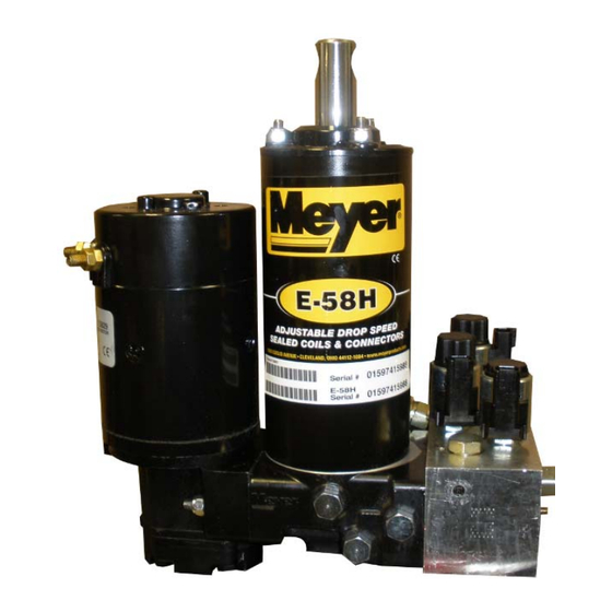
GENERAL DESCRIPTION E-58H unit is an electrically powered and electrically controlled hydraulic mechanism specifically designed for use with Meyer Snow Plows. The E-58H raises and lowers the plow with an integral 8" stroke hydraulic cylinder. In addition to raising and lowering the plow hydraulically, the E-58H angles the plow hydraulically, left and right, via remote hydraulic cylinders. - Page 8 FIGURE 1-1...
- Page 9 FIGURE 1-2...
- Page 10 FIGURE 1-3...
- Page 11 FIGURE 1-4...
-
Page 12: Solenoid Valves
The basic operating principles of the hydraulic pump Under a condition, such as when a hydraulic used in the E-58H units are quite simple. Figure 1-5 cylinder is extended to the end of its stroke, illustrates the basic components of a positive eliminating additional space for the pressurized displacement gear type pump and their functions. -
Page 13: A" Solenoid Valve
It is located next to the “C” valve on the E-58H. It has two functions: The first is to prevent the hydraulic “B”... -
Page 14: Crossover Relief Valves
Cleanliness is perhaps the single most important ingredient in assuring a hydraulic system’s reliability. Should the hydraulic fluid become contaminated, malfunction and permanent damage to the hydraulic system may occur. For this reason, all the E-58H units are equipped with a filter system consisting of: -12-... - Page 15 SECTION 2 - DIAGNOSIS CONTENTS E-58H GENERAL INFORMATION TESTING TIPS “RAISE” Troubleshooting “LEAK DOWN” Troubleshooting “LOWER” Troubleshooting “ANGLE LEFT” Troubleshooting “ANGLE RIGHT” Troubleshooting “WILL NOT HOLD ANGLE” Troubleshooting -13-...
- Page 16 E-58H Unit These charts are intended to be used as an aid in diagnosing problems on the E-58H unit. They are not a substitute for factory training and experience. Be certain to read the General Information and Testing Tips sections before attempting any troubleshooting.
- Page 17 E-58H ONLY SNOW PLOW WILL NOT RAISE Are all electrical Charge Battery - Is there power Does the Motor connections clean Clean and tighten going to Operate? and tight? all electrical the motor? Is Battery Charged? Connections. Is there power...
- Page 18 E-58H ONLY SNOW PLOW LEAKS DOWN Does the Does the snow plow snow plow drop drop and angle straight down? to the left? Replace Replace Replace "B" Check Valve "B" Valve Sump Base Does it now hold? Does it now hold? Are "A"...
- Page 19 E-58H ONLY SNOW PLOW WILL NOT ANGLE LEFT See the Raise Can the snow plow Flow Chart Raise? Section Does the motor run Is there power to Is there power Is the Touchpad when angle switch the motor solenoid? leaving the switch?
- Page 20 E-58H ONLY SNOW PLOW WILL NOT ANGLE RIGHT See the Raise Can the snow plow Flow Chart Raise? Section Are the wires in Does the motor run Is there power to Is there power molded connector the motor solenoid? when angle switch...
- Page 21 E-58H Wiring Rectangular harness w/touchpad Round harness w/pistol grip "C" White "A" "B" Black Blue (Reverse Signal) Black Ground Black Ground "C" Harness To Plow Light Vehicle Side Orange to "B" "A" harness of light modules Light Adapter "B" Harness...
- Page 22 GENERAL INFORMATION ........... UNIT DISASSEMBLY AND REASSEMBLY ....Disassembly ............. Reassembly .............. • Additional Reassembly Points ......PUMP ................Shaft Seal Replacement ......... E-58H ELECTRO LIFT ® ..................Exploded View ............Parts Breakdown ............. Disassembly Photos ..........24-33 Reassembly Photos ..........
-
Page 23: General Information
Figure 3-1 is an exploded view which applies to the 2. Using an appropriate tool, pry out the original E-58H. It should be used as the primary reference for shaft seal, being careful not to damage the shaft proper reassembly. Where necessary, this section or pump housing. -
Page 24: Exploded View
Caution: Torque to 100-125 in.-lbs. Caution: Torque to 45-55 in.-lbs. GROOVES Sealant FACE DOWN (A2) (D1) Caution: Torque to 100-125 in.-lbs. ADJUSTABLE Caution: Torque to 75-85 in. lbs. E-58H Exploded View (94) Cross-Over Relief Valve. NON ADJUSTABLE FIGURE 3-1 -22-... -
Page 25: Parts Breakdown
Parts indented are included in assembly under which they are indented. *Parts included in Master Seal Kit Part No. 15969 (E-58H), Basic Seal Kit Part No. 15254 Pump Relief Valve @ 2000 + 50 P .S.I. full flow. Non Adjustable Crossover Relief Valve @ 3800 ±... -
Page 26: Disassembly Photos
DISASSEMBLY FIGURE 3-2 FIGURE 3-3 To drain oil from the unit, remove the drain plug using a Drain Plug removed. 11/16" wrench. FIGURE 3-4 FIGURE 3-5 To replace the motor remove the two cap screws, use a Hold the motor parts together while removing it from the 10mm hex socket. - Page 27 DISASSEMBLY FIGURE 3-6 FIGURE 3-7 To remove the pump, Use a 1/2" hex socket on the three Pump removed from the unit base. locknuts. The studs usually unscrew with the nuts. FIGURE 3-8 FIGURE 3-9 Remove the “A” Coil using your hand or carefully use Coil removed from the “A”...
- Page 28 DISASSEMBLY FIGURE 3-10 FIGURE 3-11 The “A” Cartridge is removed using a 7/8" hex deep The “A” Cartridge is removed. Clean by soaking socket. cartridge in cleaning solvent. FIGURE 3-12 FIGURE 3-13 Remove the “B” Coil. The “B” Cartridge is removed using a 7/8" hex deep socket.
- Page 29 DISASSEMBLY FIGURE 3-14 FIGURE 3-15 The “B” Cartridge is removed. Clean by soaking Use a 7/8” wrench or socket to remove the “B” Check cartridge in cleaning solvent. Valve Nut. FIGURE 3-16 FIGURE 3-17 Remove “B” Check Valve Nut. Retrieve the “B” Check Valve Body. -27-...
- Page 30 DISASSEMBLY FIGURE 3-18 FIGURE 3-19 Use a magnet to retrieve the “B” Check Valve Poppet. Retrieve the “B” Check Valve Spring. The “B” Check valve poppet has been replaced by a ball. (See Service Bulletin 214) The “B” Check valve replacement kit is part number 15959.
- Page 31 DISASSEMBLY FIGURE 3-22 FIGURE 3-23 The “C” Cartridge is removed. Clean by soaking Use a 15/16” hex deep socket to remove the P.O. Check cartridge in cleaning solvent. valve assembly used for angling. FIGURE 3-24 FIGURE 3-25 Remove the P.O. Check valve assembly. Clean by Remove the P.O.
- Page 32 DISASSEMBLY FIGURE 3-26 FIGURE 3-27 Use a 15/16” hex deep socket to remove the P.O. Check Remove the P.O. Check valve assembly. Clean by valve assembly used for angling. soaking Check valve in cleaning solvent. FIGURE 3-28 FIGURE 3-29 Use a 7/8” wrench or socket to remove filter plug. Remove Filter Plug.
- Page 33 DISASSEMBLY FIGURE 3-30 FIGURE 3-31 Remove the Filter. Clean by soaking Filter in cleaning Use a 1/4" hex key or Allen Socket to remove the four solvent. valve block mounting bolts. FIGURE 3-32 FIGURE 3-33 Use a 1/4" hex key or Allen Socket to remove pilot valve Use a 11/16 Wrench or Socket to remove Crossover plug.
- Page 34 DISASSEMBLY FIGURE 3-34 FIGURE 3-35 Remove Crossover Relief Valve. There is one filter on the base assembly. Remove filters with an 11/16" wrench. FIGURE 3-37 FIGURE 3-36 Before removing ram and piston assembly, extend rod Filters removed; soak in kerosene before reassembling. fully.
- Page 35 DISASSEMBLY FIGURE 3-38 FIGURE 3-39 When disassembling the reservoir-cylinder assembly Cover is removed from reservoir using a large screw use a 1/2" hex socket to remove the lock nuts. The studs driver and hammer or mallet as shown, tapping lightly usually unscrew from the base with the nuts.
-
Page 36: Reassembly Photos
REASSEMBLY NOTE: Notch on the washer to be on underside. FIGURE 3-43 FIGURE 3-42 Install cylinder assembly carefully being certain it seats Clean all paint from ram then slide the cylinder over the squarely on “O” ring in base. Assemble O-Ring and ram piston assembly using a rubber or leather mallet. - Page 37 REASSEMBLY FIGURE 3-47 FIGURE 3-46 Torque the bolts to 100-125 in. lbs. using a 1/4” hex key Drain plug and filters to be torqued to 75-85 in. lbs. with or Allen Socket. an 11/16" hex socket. Remove nuts from pump studs and screw into base.
- Page 38 REASSEMBLY REFILL UNIT WITH MEYER M-1 HYDRAULIC FLUID FIGURE 3-50 FIGURE 3-51 Torque cap screws to 45 - 55 in. lbs., then apply Permatex Follow instructions under Form-A-Gasket No. 2 or equivalent sealant around “Replacement of Hydraulic Fluid” See POST SEASON MAINTENANCE on page 3 each cap screw head.
-
Page 39: Brush Replacement
REASSEMBLY FIGURE 3-54 Use a 11/16 Wrench or Socket to tighten Crossover Relief Valve. BRUSH REPLACEMENT OF ISKRA MOTOR - All Models FIGURE 3-55 Remove motor from hydraulic unit. Remove top cap from motor housing. To replace brushes (part # 15854) start by pushing each brush assembly towards the commutator. -
Page 40: Controller Operation
Hands-Free Plowing or ALM/ARM Meyer re-branded the ALM/ARM feature on its 22690X controllers to be Hands-Free Plowing (HFP) ™. When activated, the Hands-Free Plowing (HFP) mode uses the vehicle’s shift lever to control the up/down movement of the moldboard. Pressing the HFP button on the controller will toggle you through: On/Off, Back-drag Mode (default mode when active), and Forward Plowing Mode. -
Page 41: Specifications
Nominal resistance (ohm meter lead connected to coil lead, other meter lead connected to metal foot) 2.65 to 4.5 ohms. HYDRAULIC SPECIFICATIONS PUMP - Pressure Output E-58H (Non Adjustable) 2000 P .S.I. CROSSOVER RELIEF VALVE Opening Pressure 3800 + 400 P .S.I. - Page 42 E-58H power unit service manual Meyer Products LLC 18513 Euclid Ave. • Cleveland, Ohio 44112-1084 Phone 486-1313 (Area Code 216) www.meyerproducts.com• email info@meyerproducts.com © 2011 Printed in the U.S.A.
Need help?
Do you have a question about the E-58H and is the answer not in the manual?
Questions and answers