Table of Contents
Advertisement
Meyer Products Inc.
18513 Euclid Ave. • Cleveland, OH 44112-1084
Phone (216) 486-1313
email•warranty@meyerproducts.com
© 2005 Printed in the U.S.A.
ELECTRO LIFT
power units
service manual
www.diamondplow.com • email info@diamondplow.com
FORM NO. 1-562-R16
October, 2005
MODELS
E-46, E-46H
E-47, E-47H
E-57, E-57H
Diamond Equipment
6 Angell Lane• Damariscotta, ME 04543-9720
Phone (207) 563-2227
Price: $4.25
®
Advertisement
Chapters
Table of Contents

Related Manuals for Meyer ELECTRO LIFT E-46


Summary of Contents for Meyer ELECTRO LIFT E-46
- Page 1 ® power units service manual MODELS E-46, E-46H E-47, E-47H E-57, E-57H Meyer Products Inc. Diamond Equipment 18513 Euclid Ave. • Cleveland, OH 44112-1084 6 Angell Lane• Damariscotta, ME 04543-9720 Phone (216) 486-1313 Phone (207) 563-2227 email•warranty@meyerproducts.com www.diamondplow.com • email info@diamondplow.com...
- Page 2 GENERAL DESCRIPTION AND THEORY OF OPERATION ........DIAGNOSIS ............. REPAIR PROCEDURE ..........SPECIFICATIONS ............. Meyer Products Inc. reserves the right, under its continuing product improvement program, to change construction or design details, specifications and prices without notice or without incurring any obligation.
-
Page 3: Maintenance
SECTION 0 - GENERAL INFORMATION AND MAINTENANCE CONTENTS GENERAL INFORMATION ..........• ............ ODEL DENTIFICATION • ODEL DENTIFICATION AND ..........ERIAL UMBER OCATION • ........... OTOR DENTIFICATION MAINTENANCE ..............• ........... ENERAL AINTENANCE • ..............LEANLINESS • ........... EHICLE LECTRICAL YSTEM •... -
Page 4: L Ocation
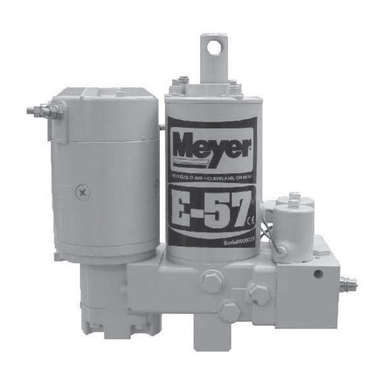
The Electro Lift unit is an electrically powered hydraulic ® mechanism specifically designed for use with the Meyer Three different brand motors are used on the Electro Snow Plow and is available in four models as follows: Lift® units American Bosch, Prestolite and Iskra. -
Page 5: H Ydraulic F Luid
Raise and lower the plow several times and with lift Meyer Products Inc. will not be liable for damages rod fully retracted, give a final check to the fluid level resulting from the use of inferior or other fluids or and replace filler plug. -
Page 6: Table Of Contents
SECTION 1 - GENERAL DESCRIPTION AND THEORY OF OPERATION CONTENTS GENERAL DESCRIPTION ....................THEORY OF OPERATION ....................• F ........................UNCTIONS •• Models E-46 and E-46H ................... •• Models E-47, E-47H and E-57, E-57H ............• E ..................6-18 LECTRICAL AND HARTS ELECTRO LIFT®... -
Page 7: General Description
The Electro Lift models perform basic functions. ® designed for use with Meyer Snow Plows. The standard Because certain of these basic functions are model E-46 raises and lowers the plow hydraulically accomplished differently in the models E-46 and with an integral 6"... - Page 12 -10-...
- Page 13 -11-...
- Page 14 -12-...
- Page 15 -13-...
- Page 16 -14-...
- Page 17 -15-...
- Page 18 -16-...
- Page 19 -17-...
- Page 20 -18-...
-
Page 21: Electro Lift® Unit Components
ELECTRO LIFT® UNIT COMPONENTS ELECTRO LIFT UNIT COMPONENTS ® MOTORS ( 3”) E-46, E-46H and E-47, E-47H The 12-volt DC high torque motor used on the Electro Lift units are interchangeable among all four models. ® Its function in all four applications is to drive the hydraulic pump. -
Page 22: Solenoid Valves
ELECTRO LIFT® UNIT COMPONENTS CONT. Under a condition, such as when a hydraulic cylinder WINDING is extended to the end of its stroke, eliminating additional space for the pressurized hydraulic oil to be pumped into, the alternate opening and closing of COIL the poppet valve controls the pump’s pressure output and provides an escape for the pressurized hydraulic... -
Page 23: Check Valves
ELECTRO LIFT® UNIT COMPONENTS CONT. CHECK VALVES Check valves are very simple devices that have two In this instance, the pressure is not produced by basic functions: They prevent fluid from passing through the pump but rather by the damaging force. As an them in one direction, but they allow fluid to pass example, assume that the right corner of the plow through them in the opposite direction. -
Page 24: Single Lever Control
The complete system (hydraulic unit, the Touch Pad. power angling cylinders and hoses) should be flushed. Flush the system with Meyer Hydra-Flush™ Fluid M-2. -22-... -
Page 25: Diagnosis
SECTION 2 - DIAGNOSIS CONTENTS GENERAL INFORMATION ................24 TESTING TIPS ....................24 “RAISE” Troubleshooting ................25 “LEAK DOWN” Troubleshooting ..............26 “LOWER” Troubleshooting ................26 “ANGLE LEFT” Troubleshooting ..............27 “ANGLE RIGHT” Troubleshooting ............... 28 “WILL NOT HOLD ANGLE” Troubleshooting ..........29 “CROSSOVER RELIEF VALVE”... - Page 26 Note: The E-57 Electro Lift ® Unit has a non adjustable pressure relief valve. 7. Flush the complete system including unit, hoses and power angling rams with Meyer Hydra-Flush™ Fluid M-2. To Ignition Switch (Accessory Side)
- Page 27 SNOW PLOW WILL NOT RAISE Charge Battery - Are all electrical Is there power Does the Clean and tighten connections clean going to Motor Operate? all electrical and tight? the motor? Connections. Is Battery Charged? Is there power Inspect Motor - Is there power leaving the Remove motor.
- Page 28 SNOW PLOW LEAKS DOWN Does the Does the snow plow snow plow drop drop and angle straight down? to the left? Replace Replace Replace "B" Check Valve "B" Valve Sump Base Does it now hold? Does it now hold? Are "A" Valve O-rings Replace O-Rings in good condition? Does "A"...
- Page 29 SNOW PLOW WILL NOT ANGLE LEFT See the Raise Can the snow plow Flow Chart Raise? Section Are the wires in Does the motor run Is there power to Is there power molded connector when angle switch the motor solenoid? leaving the switch? making contact with is pushed?
- Page 30 SNOW PLOW WILL NOT ANGLE RIGHT See the Raise Can the snow plow Flow Chart Raise? Section Are the wires in Does the motor run Is there power to Is there power molded connector when angle switch the motor solenoid? leaving the switch? making contact with is pushed?
- Page 31 SNOW PLOW WILL NOT HOLD ANGLE Is Crossover Relief set Set Crossover Relief to Are the Rams mushy? Are the "C" Valve Does the moldboard 3800 + 400 P.S.I. at 3800 + 400 P.S.I.? Can you push the moldboard O-Rings in poor hold left angle &...
-
Page 32: Repair Procedure
SECTION 3 - REPAIR PROCEDURES CONTENTS GENERAL INFORMATION ..............UNIT DISASSEMBLY AND REASSEMBLY ........Disassembly ..................Reassembly ..................• Additional Reassembly Points ........... PUMP ...................... Shaft Seal Replacement ..............ELECTRO LIFT ® Exploded View ................Parts Breakdown ................Disassembly Photos ............... 34-41 Reassembly Photos ................ -
Page 33: General Information
GENERAL INFORMATION Reassembly Using the proper guidelines and precautions, all four model Electro Lift units are easy to disassemble and ® reassemble. Figure 3-1 (page 32) is an exploded view See Figures 3-31 through 3-41 (pages 41-43) for which applies to all four models. It should be used as important reassembly points on any of the four models. -
Page 34: Electro Lift Exploded View
ELECTRO LIFT ® Exploded View Caution: Torque to Caution: 100-125 in.-lbs. Torque to 10 in.-lbs. Caution: Torque to 100-125 in.-lbs. Caution: Torque to Notch on 45-55 in.-lbs. underside Sealant (A2) (D1) Caution: Torque to 100-125 in.-lbs. Backup O Ring O Ring Backup O Ring Backup... -
Page 35: Parts Breakdown
PARTS BREAKDOWN E-46, E-47 & E-47H E-57 & E-57H ELECTRO-LIFT ® PARTS LIST STANDARD- LONG STROKE- STANDARD- LONG STROKE- UP THROUGH HM-9 & HM-10 UP THROUGH HM-9 & HM-10 ONLY ONLY ITEM 1-1/8" x 6" Stroke 1-1/8" x 8" Stroke QTY. -
Page 36: Disassembly Photos
DISASSEMBLY - ALL MODELS FIGURE 3-2 FIGURE 3-3 To drain oil from the unit, remove the drain plug using a Drain Plug removed. 11/16" wrench. E-46, E-46H & E-47, E-47H E-46, E-46H & E-47, E-47H FIGURE 3-4 FIGURE 3-5 To replace the motor remove the two cap screws, use a Hold the motor parts together while removing it from the 10mm hex socket on the E-57 and a 3/8"... - Page 37 DISASSEMBLY - ALL MODELS E-46, E-46H & E-47, E-47H E-46, E-46H & E-47, E-47H FIGURE 3-6 FIGURE 3-7 To remove the pump, E-57 use a 1/4” Allen socket on Pump removed from the unit base. the three bolts. E-46 and E-47 use a 1/2" hex socket on the three locknuts.
- Page 38 DISASSEMBLY - ALL MODELS FIGURE 3-10 FIGURE 3-11 The “A” Cartridge is removed using a 7/8" or 1-1/8" hex The “A” Cartridge is removed. Clean screen by soaking deep socket. cartridge in cleaning solvent. E-46 & E-46H ONLY FIGURE 3-12 FIGURE 3-13 End plate is removed by using a 1/4"...
- Page 39 DISASSEMBLY - E-47 and E-57 MODELS FIGURE 3-14 FIGURE 3-15 Coils removed from cartridges. A special hex socket, part number 21891, may be required to remove “B” and “C” Cartridges. (See Figure 3-67) FIGURE 3-16 FIGURE 3-17 “B” & “C” Cartridge being removed from valve block. A magnetic probe is extremely useful for removal of Clean cartridges by soaking in kerosene.
- Page 40 DISASSEMBLY - E-47 & E-57 MODELS FIGURE 3-18 FIGURE 3-19 “B” Cartridge check spring removed. Use a 13/16” Hex Socket to remove pilot valve plug. FIGURE 3-20 FIGURE 3-21 Pilot check piston being removed. Handle piston with The valve body can be removed from unit using care.
- Page 41 DISASSEMBLY - E-47 & E-57 MODELS FIGURE 3-22 FIGURE 3-23 Use a 1/4" hex key or Allen Socket to remove pilot valve Pilot check spring being removed from valve body. plug. FIGURE 3-24 FIGURE 3-25 Pilot check ball removed. This is a 3/8" diameter steel There are two filters on E-47 and E-47H and one on ball.
- Page 42 DISASSEMBLY - ALL MODELS FIGURE 3-27 FIGURE 3-26 Before removing ram and piston assembly, extend rod Filters removed; soak in kerosene before reassembling. fully. This drains out remaining oil in cylinder. FIGURE 3-28 FIGURE 3-29 When disassembling the reservoir-cylinder assembly Cover is removed from reservoir using a large screw use a 1/2"...
-
Page 43: Reassembly Photos
FIGURE 3-30 FIGURE 3-31 Remove ram and cylinder assembly from reservoir then Remove nuts, baffle and retainer rings from studs and pull ram out of cylinder. Worn packing cup on piston screw the studs into the base. Clean reassemble Sump should be replaced if cloth backing is visible. - Page 44 REASSEMBLY - ALL MODELS FIGURE 3-35 FIGURE 3-34 Install cover assembly using mallet to seat cover, making Reinstall reservoir using mallet to seat reservoir certain filter plug is properly located. squarely. E-46, E-46H & E-47, E-47H FIGURE 3-36 FIGURE 3-37 Drain plug and filters to be torqued to 75-85 in.
- Page 45 On the E-57 use a 1/4” Allen socket on the bolts and on the E-46 and E-47 use a 1/2" hex socket on the locknuts. E-46, E-46H & E-47, E-47H REFILL UNIT WITH MEYER M-1 HYDRAULIC FLUID FIGURE 3-40 FIGURE 3-41 Torque cap screws to 45 - 55 in.
-
Page 46: Crossover Relief Valve Disassembly
CROSSOVER RELIEF VALVE DISASSEMBLY FIGURE 3-43 FIGURE 3-42 Remove Plug (58) and adjusting Screw (59) using a Remove Acorn Nut (61), O-ring (60) using a 15/16” open 3/8” open end wrench. end wrench. FIGURE 3-45 FIGURE 3-44 Remove Pressure Spring (55) Remove Plug (58), Adjusting Screw (59) and Disc (57). - Page 47 CROSSOVER RELIEF VALVE DISASSEMBLY FIGURE 3-47 FIGURE 3-46 Remove Cage (50), O-ring (49) using special tool. Remove Poppet (52), Guide (54), Washer (53), Spacer (56). FIGURE 3-48 Remove bottom O-ring (48) using special tool. -45-...
-
Page 48: Reassembly
CROSSOVER RELIEF VALVE REASSEMBLY FIGURE 3-49 FIGURE 3-50 Correct order when reassembling Crossover Relief Valve Reinstall O-ring (48) making certain it is seated to the (47). Note: All parts should be dipped in oil prior to their bottom of the cavity. assembly. - Page 49 CROSSOVER RELIEF VALVE REASSEMBLY FIGURE 3-53 FIGURE 3-54 Assemble Poppet with bushing into Cage as shown. To install Bushing (51), assemble Washer (53) onto the Poppet as shown. Press Washer down on Cage, this will put equal pressure on the Bushing. Hold Washer (53) in place then remove Poppet from Cage.
- Page 50 CROSSOVER RELIEF VALVE REASSEMBLY FIGURE 3-57 FIGURE 3-58 Reassemble Poppet (52) into Cage. Reassemble Washer (53) smooth side up. FIGURE 3-60 FIGURE 3-59 Reassemble Spring guide (54) smooth side down. Assemble Spacer (56). -48-...
- Page 51 CROSSOVER RELIEF VALVE REASSEMBLY FIGURE 3-61 FIGURE 3-62 Reassemble Spring (55). Reassemble Plug (58) with Adjusting Screw (59) and disc (57). To properly adjust the Crossover Relief Valve refer to page 21. Push leading edge of the Moldboard against an immovable object until Crossover Relief Valve opens. (3800 P.S.I.
-
Page 52: Brush Replacement
BRUSH REPLACEMENT OF AMERICAN BOSCH MOTOR FIGURE 3-64 FIGURE 3-65 A special tool figure 3-69 is required to hold brushes in Once top cap is positioned over armature shaft, carefully motor top cap as shown. slide tool out while pushing down on cap. BRUSH REPLACEMENT OF ISKRA MOTOR FIGURE 3-66 Remove motor from hydraulic unit. -
Page 53: American Bosch Brush Replacement
BRUSH REPLACEMENT VALVE CARTRIDGES “A”, “B” and “C” American Bosch Brush Replacement IMPORTANT: The valve cartridges can be damaged beyond repair by bending or denting the tube, the The commutator end cap is removed by removing portion of the cartridge surrounded by the coil. the hex head cap screws as shown in Figure 3-4 Therefore, do not grip the cartridge tube with pliers or clamp it in a vise. -
Page 54: Special Tools
SPECIAL TOOLS Crossover Relief Valve Inner Harden Steel Wire from a Throttle/Choke cable 7.00" 0.13" FIGURE 3-67 “B” and “C” Cartridge Tool, #21891. FIGURE 3-68 0.75" 0.38" R 0.25" 3.00" 2.00" 1.00" 0.25" x 45 Degree 6 Places 1.50" Bend Area 2.12"... -
Page 55: Specifications
SPECIFICATIONS ELECTRICAL SPECIFICATIONS SOLENOID SWITCH Applied Voltage 12 Volts DC MOTOR Max. Current Draw 5 Amperes American Bosch M0551046A Nominal resistance (ohm meter lead connected to coil No load (motor not attached to pump) lead, other meter lead connected to metal foot) NOTE: Do not operate motor continuously for 2.65 to 4.5 ohms. - Page 56 ® power units service manual MODELS E-46, E-46H E-47, E-47H E-57, E-57H Meyer Products Inc. Diamond Equipment 18513 Euclid Ave. • Cleveland, OH 44112-1084 6 Angell Lane• Damariscotta, ME 04543-9720 Phone (216) 486-1313 Phone (207) 563-2227 email•warranty@meyerproducts.com www.diamondplow.com • email info@diamondplow.com...
Need help?
Do you have a question about the ELECTRO LIFT E-46 and is the answer not in the manual?
Questions and answers