Table of Contents
Advertisement
Quick Links
FORM NO. 1-667R7
October 2005
Price: $5.00
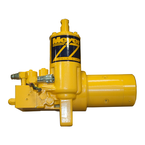
QUIK-LIFT
®
power unit
service manual
MODELS
E-60, E-60H
Meyer Products
Diamond Equipment
18513 Euclid Ave. • Cleveland, OH 44112-1084
6 Angell Lane• Damariscotta, ME 04543-9720
Phone (216) 486-1313
Phone (207) 563-2227
www.diamondplow.com • email info@diamondplow.com
email•warranty@meyerproducts.com
© 2005 Printed in the U.S.A.
Advertisement
Table of Contents


Need help?
Do you have a question about the E-60 QUIK-LIFT and is the answer not in the manual?
Questions and answers