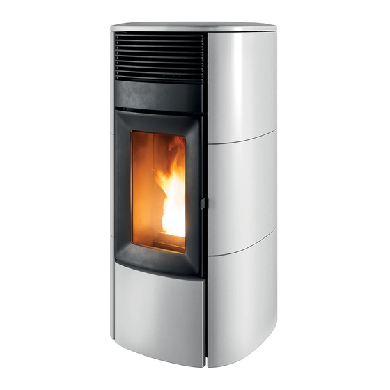
MCZ SUITE COMFORT AIRMATIC 14 M2 Installation Manual
Sealed pellet stove
Hide thumbs
Also See for SUITE COMFORT AIRMATIC 14 M2:
- Installation manual (52 pages) ,
- Operation and cleaning (72 pages) ,
- Installation manual (68 pages)

Related Manuals for MCZ SUITE COMFORT AIRMATIC 14 M2


Summary of Contents for MCZ SUITE COMFORT AIRMATIC 14 M2
- Page 1 INSTALLATION GUIDE SEALED PELLET STOVE SUITE COMFORT AIRMATIC 14 M2 CLUB COMFORT AIRMATIC 14 M2 PART 1 - REGULATIONS AND ASSEMBLY Translation of original instructions...
-
Page 2: Table Of Contents
TABLE OF CONTENTS TABLE OF CONTENTS ....................II INTRODUCTION ......................1 1-WARNINGS AND WARRANTY CONDITIONS ..............2 2-INSTALLATION ......................9 3-DRAWINGS AND TECHNICAL SPECIFICATIONS ............17 4-UNPACKING ......................19 5-SUIT/CLUB STOVE ASSEMBLY ..................22 6-DOOR OPENING .....................37 7-CONNECTIONS TO ADDITIONAL DEVICES ..............38 8-ELECTRICAL CONNECTION..................40 9-LOADING THE PELLETS ...................41... -
Page 3: Introduction
No part of this manual may be translated into other languages, adapted and/or reproduced, even in part, in other mechanical and/or electronic form or media, for photocopies, recordings or other, without the prior written authorisation of MCZ Group Spa. The company reserves the right to make changes to the product at any time without prior notice. The owner company reserves its rights according to law. -
Page 4: 1-Warnings And Warranty Conditions
1-WARNINGS AND WARRANTY CONDITIONS SAFETY WARNINGS • The installation, electrical connection, operating test and maintenance must only be carried out by a qualified operator. • Install the product in compliance with the laws and regulations in force. • Only use the fuel recommended by the manufacturer. The product must not be used as an incinerator. - Page 5 1-WARNINGS AND WARRANTY CONDITIONS • Do not dry laundry on the product. Any drying racks or the like must be kept at a safe distance from the product. Fire hazard. • The product maintenance operations must be exclusively carried out by a qualified operator on a yearly basis.
- Page 6 1-WARNINGS AND WARRANTY CONDITIONS • Do not allow the product to come into contact with water, it contains live electrical parts. • Do not wash the product with water (or other liquids) as they could penetrate inside the unit, damaging the electrical insulation with the risk of electrocution. • Do not use detergents to wash the stove, they could damage the aesthetic parts of the product.
- Page 7 1-WARNINGS AND WARRANTY CONDITIONS • The sound pressure level of this appliance does not exceed 70 dB(A). • Live electrical parts: only power the product once it has been fully assembled. • Disconnect the product from the 230V power supply before performing any maintenance operations.
- Page 8 1-WARNINGS AND WARRANTY CONDITIONS INFORMATION: • Please contact the retailer or qualified personnel for any information, problem or malfunction. • Only use the fuel specified by the manufacturer. • When the product is switched on for the first time, it is normal for it to emit smoke due to the paint heating up for the first time. Therefore make sure the room it is installed in is well-ventilated.
- Page 9 1-WARNINGS AND WARRANTY CONDITIONS WARRANTY CONDITIONS For the duration, terms, conditions, limitations of the MCZ conventional warranty, please refer to the specific warranty card that is included with the product. Information for management of waste electrical and electronic equipment containing batteries and accumulators This symbol appears on the product, on the batteries, on the accumulators or on their packaging or on their documentation;...
- Page 10 1-WARNINGS AND WARRANTY CONDITIONS Our solid bio-combustible products, (hereinafter called “Products”) are designed and manufactured in compliance with one of the following European standard harmonised to Regulation (UE) no. 305/2011 for construction products: EN 14785: “Residential space heating appliances fired by wood pellets” EN 13240: “Room heaters fired by solid fuel.”...
-
Page 11: 2-Installation
2-INSTALLATION The instructions in this chapter refer explicitly to the Italian installation regulation UNI 10683. In any case, always observe the regulations in force in the country of installation. PELLETS The pellet is obtained from natural dried wood sawdust (without paint). The compactness of the material is guaranteed by the lignin contained in the wood itself, without glue or binders. - Page 12 2-INSTALLATION FOREWORD The heating system (generator + combustion air supply + combustion product expulsion system + any hydraulic/aeraulic system) must be installed in compliance with the laws and regulations in force , and carried out by a qualified technician, who must issue a declaration of conformity of the system to the system manager and shall undertake full responsibility for final installation and consequent good operation of the product.
- Page 13 2-INSTALLATION MINIMUM DISTANCES Observe the distances from flammable objects (sofas, furniture, wood panelling, etc..) as specified in the following diagram. If objects considered to be particularly sensitive to heat are present, such as furniture, curtains or sofas, as a precaution, increase the stove clearances substantially to avoid possible deterioration due to the effect of heat.
- Page 14 2-INSTALLATION In any case, ensure adequate distance to facilitate access during cleaning and extraordinary maintenance. If this is not possible, it must still be possible to distance the product from adjacent walls/elements. This operation must be performed by a technician qualified to disconnect the combustion product expulsion ducts and their subsequent restoration.
- Page 15 2-INSTALLATION Below 15kW: Air duct diameter Maximum length Maximum length (smooth duct) (corrugated duct) 50mm 60mm 80mm 100mm Above 15kW: Air duct diameter Maximum length Maximum length (smooth duct) (corrugated duct) 50mm 60mm 80mm 100mm Technical Dept. - All rights reserved - Reproduction prohibited...
- Page 16 2-INSTALLATION Preparing the smoke expulsion system The combustion product expulsion system is a particularly important element for the proper operation of the appliance and must be correctly sized according to EN 13384-1. Its creation/adaptation/verification must always be carried out by a legally qualified operator and must comply with the regulations in force in the country where the appliance is installed.
- Page 17 2-INSTALLATION Chimneypot The chimneypot, meaning the end part of the flue, must meet the following characteristics: • the smoke outlet section must be at least double the internal section of the chimney; • prevent the penetration of rain or snow; •...
- Page 18 2-INSTALLATION EXAMPLES OF INSTALLATION (DIAMETERS AND LENGTHS TO BE SIZED) 1. Flue installation with hole for the passage of the pipe increased by: • minimum 100mm around the pipe if next to non-flammable parts such as cement, brick, etc.; or •...
-
Page 19: 3-Drawings And Technical Specifications
3-DRAWINGS AND TECHNICAL SPECIFICATIONS DRAWINGS AND CHARACTERISTICS SUITE/CLUB COMFORT AIRMATIC 14 M2 STOVE DIMENSIONS Ø50 Ø80 Ø80 Technical Dept. - All rights reserved - Reproduction prohibited... - Page 20 3-DRAWINGS AND TECHNICAL SPECIFICATIONS TECHNICAL SPECIFICATIONS SUITE/CLUB COMFORT AIRMATIC 14 M2 Energy Efficiency Class Nominal output power 13.8 kW (11868 kcal/h) Minimum power output 3.4 kW (2924 kcal/h) Efficiency at Max 90.5% Efficiency at Min 93.2% Temperature of exhaust smoke at Max 205 °C Temperature of exhaust smoke at Min 106 °C...
-
Page 21: 4-Unpacking
4-UNPACKING PREPARATION AND UNPACKING The packaging consists of a recyclable cardboard box in line with RESY standards and a wooden pallet. All packaging materials can be reused for similar use or eventually disposed of as urban solid waste, in compliance with the regulations in force. After having removed the packaging make sure the product is intact. - Page 22 4-UNPACKING REMOVING THE FASTENING BRACKETS (SUITE/CLUB STOVES) To remove the SUITE/CLUB stove from the pallet, you must remove the two screws “u” and plate “s” from the stove’s foot. There are four brackets “s”.
- Page 23 4-UNPACKING Position the stove and connect it to the flue. Use the 4 adjustable feet (J) to get the stove correctly levelled so that the smoke outlet is lined up with the connecting pipe. If the stove needs to be connected to an outlet pipe which goes through the rear wall (to connect to the flue), take the utmost care to make sure that the joint is not forced.
-
Page 24: 5-Suit/Club Stove Assembly
5-SUIT/CLUB STOVE ASSEMBLY Live electrical parts: only power the product once it has been fully assembled. On delivery, the Suite and Club stoves have no ceramic cladding, as shown in the image below. Take the box with the ceramics (figure below) and prepare them for installation. The ceramics are already completely assembled (ceramics and mounting brackets) and must be mounted as per the attached diagram, “Side panels assembly”... - Page 25 5-SUIT/CLUB STOVE ASSEMBLY INSTALLING THE SIDE PANELS There are codes on the internal part of the ceramics to help correctly position them. As shown in the following image, on the right side they are called D1/D2/D3 and on the left side S1/S2/S3, to be placed from the bottom upwards. Technical Dept.
- Page 26 5-SUIT/CLUB STOVE ASSEMBLY REMOVING THE CERAMIC PANELS FASTENING FRAME Remove the two screws “x” and the two notched washers “z” from the top part. Attention! The two screws “x” and the two notched washers “z” must be used again to secure the frame with the ceramic panels.
- Page 27 5-SUIT/CLUB STOVE ASSEMBLY Make the holes “V” of the frame “S” come out from the hooks “L” on the structure of the stove. Technical Dept. - All rights reserved - Reproduction prohibited...
- Page 28 5-SUIT/CLUB STOVE ASSEMBLY Take the template “U” from the structure’s packaging, which must be used to position the ceramic panels correctly. The part of the template marked “FRONT RIGHT” must be positioned as indicated in the picture, towards the front part of the stove. Use the two screws “k”...
- Page 29 5-SUIT/CLUB STOVE ASSEMBLY From the ceramic panels packaging, take the three ceramic panels marked “D1”, “D2”, “D3”. Place a sheet or cloth on the floor “T” to avoid scratching or damaging the ceramic panels during assembly. Place the three ceramic panels on the sheet “T” on the floor, as indicated in the picture. Take the frame “S”...
- Page 30 5-SUIT/CLUB STOVE ASSEMBLY Now, take the 12 screws “m” and 12 washers “n” from the ceramic panel package. Secure the frame “S” to the ceramic panels using the screws “m” and washers “n”. After securing the frame/ceramic panels, remove the two screws “k” and remove the template “U”.
- Page 31 5-SUIT/CLUB STOVE ASSEMBLY Lift the three ceramic panels with the frame and secure it to the stove’s structure. At the bottom, insert the holes “V” on the frame of the ceramic panels into the hooks “L” fitted on the structure of the stove. Technical Dept.
- Page 32 5-SUIT/CLUB STOVE ASSEMBLY On the top, secure the frame to the structure with the two screws “x” and notched washers “z” that were previously removed with the frame “S”. Attention! The frame with the ceramic panels has slotted holes “f” to adjust the ceramic panels with the front parts of the stove.
- Page 33 5-SUIT/CLUB STOVE ASSEMBLY Repeat the same operation also for the ceramic panels marked “S1”, “S2”, “S3”. Technical Dept. - All rights reserved - Reproduction prohibited...
- Page 34 5-SUIT/CLUB STOVE ASSEMBLY INSTALLING THE FRONT LOWER CERAMIC PANEL Remove the two screws “j” from the structure of the stove and remove the bracket “O”. Take the ceramic panel “B” from the package of the ceramic panels. Remove the M4x16 screw “g” from the lower part of the bracket “O”.
- Page 35 5-SUIT/CLUB STOVE ASSEMBLY Insert the bracket “O” into the frame of the ceramic panel “B” and secure it in the lower part with the screw “g” you have just removed. Now secure the ceramic panel “B” to the structure of the stove using the two screws “j”. Technical Dept.
- Page 36 5-SUIT/CLUB STOVE ASSEMBLY ADJUSTING THE LOWER PANEL It is possible to adjust the magnet “r” from the screw “v”. Then, try to bring the ceramic panel “B” flush with the door of the firebox by adjusting the magnet “r”.
- Page 37 5-SUIT/CLUB STOVE ASSEMBLY ASSEMBLING THE TOP At this point, the side panels are assembled, as well as the lower panel. Before proceeding with placing the top “A”, perform a final check of the position of the side panels. Make sure they are in line with the front panels and the door. If necessary, adjust them from the slots on the frame of the side ceramic panels.
- Page 38 5-SUIT/CLUB STOVE ASSEMBLY REMOVING THE UPPER PANEL Panel “F” is already fixed to the stove structure, it may be removed in the event of maintenance, servicing or cleaning. After removing any top, remove screws “k”, two on the right and two on the left, and remove the top front panel “F”.
-
Page 39: 6-Door Opening
6-DOOR OPENING OPENING THE DOOR OF THE FIREBOX To open the firebox door “F”, insert the cold handle “Z” into the hole in the handle “P” and pull it towards you. Attention! Only open the door when the stove is off and cold. OPENING THE DOOR OF THE FIREBOX LOWER DOOR OPENING LOWER DOOR OPENING... -
Page 40: 7-Connections To Additional Devices
7-CONNECTIONS TO ADDITIONAL DEVICES Comfort Air ducting Comfort Air stoves can channel the air into other rooms through the connection with the accessory pipes to the rear “S” shaped flange provided as per standard. The outlet air pipe can reach very high temperatures, even around 150°C: therefore, it must be adequately insulated with suitable material, especially points that could come in contact with flammable surfaces or parts that are affected by heat (e.g. - Page 41 7-CONNECTIONS TO ADDITIONAL DEVICES Attention! It is mandatory to install the vents with “V” netting (1 or 2 depending on the type of appliance) on the rear “S” output for safety purposes and to prevent the rear wall from being hit directly by the hot air flow, generating halos, blackening or even dangerous heating in the case of flammable walls.
-
Page 42: 8-Electrical Connection
8-ELECTRICAL CONNECTION ELECTRICAL CONNECTION First connect the power cable to the back of the stove and then to a wall socket. It is recommended to disconnect the power cable when the stove is not used. ELECTRICAL STOVE CONNECTION The cable must never come into contact with the smoke exhaust pipe or any other part of the stove. STOVE POWER SUPPLY Connect the power cable to the back of the stove and then to a wall socket. -
Page 43: 9-Loading The Pellets
9-LOADING THE PELLETS LOADING THE PELLETS Fuel is loaded from the upper part of the stove by lifting door “W”. Pour the pellets in slowly so that they are deposited at the bottom of the hopper. If loading pellets when the stove is running, open the door of the tank using the cold handle that comes with the stove itself. - Page 44 MCZ GROUP S.p.A. Via La Croce n°8 33074 Vigonovo di Fontanafredda (PN) – ITALY Telephone: 0434/599599 a.s. Fax: 0434/599598 Website: www.mcz.it e-mail: mcz@mcz.it 8902114100 REV.0 26/10/2021...
Need help?
Do you have a question about the SUITE COMFORT AIRMATIC 14 M2 and is the answer not in the manual?
Questions and answers