Table of Contents
Advertisement
Quick Links
Advertisement
Table of Contents

Subscribe to Our Youtube Channel
Related Manuals for SUTO S320


Summary of Contents for SUTO S320
- Page 1 English Instruction and Operation Manual S320 Display...
- Page 2 The device is destined exclusively for the described application. SUTO offers no guarantee for the suitability for any other purpose. SUTO is also not liable for consequential damage resulting from the delivery, capability or use of this device.
-
Page 3: Table Of Contents
6.2 Electrical Connection .............9 6.2.1 AC Power Supply and Alarm Connection (A1640)....10 6.2.2 DC Power Supply and Alarm Connection (A1641)....10 6.2.3 Signals at Back Terminals..........11 6.2.4 Connection of SUTO Sensors...........12 6.2.5 Connection of Third-Party Analog Sensors......13 7 Configuration ................14 8 Operation ................15 8.1 Description of Display Icons..........15... -
Page 4: Safety Instructions
• Consider all regulations for electrical installations. • The system must be disconnected from any power supply during maintenance work. • Any electrical work on the system is only allowed by authorized qualified personal. S320... - Page 5 • Make sure that the transportation temperature of the display is between -30 ... +70°C. • For transportation it is recommended to use the packaging which comes with the display. • Please make sure that the storage temperature of the display is between 0 ... +40°C. S320...
-
Page 6: Application
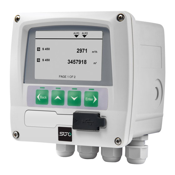
The S320 display can display all relevant parameters (flow, dew point, pressure, temperature, power consumption, compressor status etc.) in a compressed air system. The S320 display and data logger is not developed to be used in explosive areas. For the use in explosive areas please contact the manufacturer. -
Page 7: Technical Data
Sensor supply 24 V, 10 W 4.3 Input-Signals Digital input 1 x SDI for SDI input for SUTO sensors Analog input 1 x 0 ... 20 mA or 1 x 4 ... 20 mA or 1 x 0 ... 10 V 4.4 Output-Signals... -
Page 8: Dimensional Drawing
5 Dimensional Drawing 5 Dimensional Drawing S320... -
Page 9: Installation
The instrument can either be mounted into a panel or if ordered with the optional wall casing on a wall. Please observe the drawings in chapter 5 for details. The housing of the S320 must be fixed on the wall using suitable dowels and screws. -
Page 10: Ac Power Supply And Alarm Connection (A1640)
6 Installation 6.2.1 AC Power Supply and Alarm Connection (A1640) AC power connection: AC alarm connection: 6.2.2 DC Power Supply and Alarm Connection (A1641) DC power connection: DC alarm connection: S320... -
Page 11: Signals At Back Terminals
• 4 ... 20 mA signals from flow sensor or dew point sensors can be looped through the G terminal pin 5 + 2. The external device (PLC or mA-meter) negative signal is connected to pin 1. • Analog sensors are connectable to terminal I. S320... -
Page 12: Connection Of Suto Sensors
Looping the analog output of SUTO dew point sensors to a PLC It is possible to connect a SUTO dew point sensor via SDI to the S320 and at the same time use the analog output of the SUTO sensor to be connected to an external PLC or analog input card. -
Page 13: Connection Of Third-Party Analog Sensors
Connection Scheme External PLC / Analog Module S320 SUTO Dew point sensor 3-wire analog S699 2xxx 6.2.5 Connection of Third-Party Analog Sensors S320 External analog sensor Pin Signal Process signal Voltage (0… 1 V / 0… 10 V) Signal ground (internally connected to I.4 -V... -
Page 14: Configuration
This software is called S4C which can be downloaded from the company web page. To change certain or all settings by the user, S320 can be connected to the PC via the USB interface. After starting S4C all device settings are accessible. -
Page 15: Operation
• To confirm the setting change or enable an option in all setting state. After pressing the enter button, different submenus can be selected. The particular submenus will be explained in the next chapters. S320... -
Page 16: Sensor Setting
8.3 Alarm Setting The S320 has two alarm relay outputs. It is possible to set the value and the direction of the value for “Alarm 1” and “Alarm 2”. 8.4 System Status and Settings Please press the “System”... -
Page 17: Signal Outputs
The sensor, the accessories and its packings must be disposed according to your local statutory requirements. The dispose can also be carried by the manufacturer of the product, for this please contact the manufacturer. S320... - Page 18 S320...
- Page 19 S320...
- Page 20 SUTO iTEC GmbH SUTO iTEC (ASIA) Co., Ltd. Grißheimer Weg 21 Room 10, 6/F, Block B, Cambridge Plaza D-79423 Heitersheim 188 San Wan Road, Sheung Shui, N.T. Germany Hong Kong Tel: +49 (0) 7634 50488 00 Tel: +852 2328 9782 Email: sales@suto-itec.com...
Need help?
Do you have a question about the S320 and is the answer not in the manual?
Questions and answers