Table of Contents
Advertisement
Quick Links
Advertisement
Table of Contents

Related Manuals for SUTO S305


Summary of Contents for SUTO S305
- Page 1 English Instruction and Operation Manual S305 Dew Point Monitor...
- Page 2 The device is destined exclusively for the described application. SUTO offers no guarantee for the suitability for any other purpose. SUTO is also not liable for consequential damage resulting from the delivery, capability or use of this device.
-
Page 3: Table Of Contents
7.4.3 DC Power Supply and Alarm Connection ......13 7.4.4 Signals of Terminals............13 7.4.5 Pin Assignment..............14 7.4.6 Connect an Additional Analog Sensor to S305....14 7.4.7 Anschluss der externen Alarmeinheit an die S305-Relais ..15 8 Configuration ................16 9 Operation ................16 9.1 Description of Keys..............16 9.2 Sensor Settings..............17... -
Page 4: Safety Instructions
• Consider all regulations for electrical installations. • The system must be disconnected from any power supply during maintenance work. • Any electrical work on the system is only allowed by authorized qualified personal. S305... - Page 5 • Please make sure that the storage temperature of the monitor is between 0 ... +40°C. • Avoid direct UV and solar radiation during storage. • For the storage the humidity must be <90%, no condensation. S305...
-
Page 6: Registered Trademarks
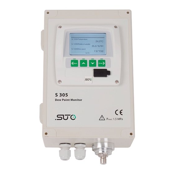
The S305 is an all-in-one Dew Point Monitor that integrates the S217 dew point meter and a display in a rugged housing (IP65). The S305 is mainly used in the compressed air systems in an industrial environment. It is not developed to be used in explosive areas. -
Page 7: Technical Data
100 ... 240 VAC, 15 VA (D699 3050 / 3052) 18 ... 30 VDC, 20 W (D699 3051 / 3053) 5.3 Input Signals Digital input 1 x SDI for dew point Analog input 0 ... 20 mA / 4 ... 20 mA, 0 ... 10 V S305... -
Page 8: Output Signals
2 relays, 230 VAC, 3A , change over contact 5.5 Accuracy Accuracy ±2°C Td(see picture below) Repeatability ±0.5°C Stated accuracy at Ambient/process temperature 23°C ± 3°C Ambient/process humidity <95% rH, no condensation Airflow > 2 l/min at sensor tip Accuracy: Valid working range: S305... -
Page 9: Dimensional Drawing
Please make sure that all components listed below are included in your package. Qty Description Item No. in wall-mounted D699 3050 S305 Dew Point Monitor D699 3051 housing D699 3052 D699 3053 USB cable, USB 2.0, A-male to A-male, 1.5 m... -
Page 10: Installation Requirements
7 Installation 7.1 Installation Requirements The device can be mounted on a wall. Please observe the drawings in chapter 6 for details. The housing of the S305 must be fixed on the wall using suitable dowels and screws. 7.2 Installation Procedure The instrument is mounted on a wall. -
Page 11: Sensor Change
7.3 Sensor Change In case of service or calibration, the sensor unit may have to be replaced. 1. Open the S305 case and remove the sensor cable connected at the display terminal first. See the left picture. -
Page 12: Electrical Connection
7 Installation 7.4 Electrical Connection 7.4.1 Layout of Terminal Blocks The following diagram is the layout of terminal blocks at the S305 back side. 7.4.2 AC Power Supply and Alarm Connection AC power connection: AC alarm connection: S305... -
Page 13: Dc Power Supply And Alarm Connection
Negative signal connection to PLC Positive analog sensor supply Negative analog sensor supply +20 mA Positive current input SGND Signal ground (internally connected to -V +10 V Positive voltage input Remark: Analog sensors can be connected to terminal I. S305... -
Page 14: Pin Assignment
7 Installation 7.4.5 Pin Assignment This following table lists the pin wirings for S305 with its internal S217. The table also shows the current signal which can be used to connect the S305 to a SPS. S305 S217 Terminal Pin... -
Page 15: Anschluss Der Externen Alarmeinheit An Die S305-Relais
7.4.7 Connect the External Alarm Unit to S305 Relays The picture below shows the connection of the external alarm unit to the S305 utilizing the alarm relays. The pre-alarm will trigger the LED and the main-alarm will then trigger the buzzer. The alarm threshold values can be set using the on screen menu under Alarm Settings. -
Page 16: Configuration
The S305 is delivered with specific customer settings according to the order. Using the S305 display and keys, you can change most settings of the S305 (including its internal S217). To change the remaining settings, you need to use the S4C-Display. -
Page 17: Sensor Settings
You can change setting for a sensor by selecting the terminal that the sensor is connected to. 9.3 Alarm Settings The S305 has two alarm relay outputs. You can set the value and the direction of the value for “Alarm 1” and “Alarm 2”. 9.4 System Status and Settings The submenus of the System settings are described below. -
Page 18: Service Settings
To view and change contact information of the service company. 10 Signal Inputs 10.1 Digital Input The S305 has one SDI input for connecting an SUTO dew point sensor. 10.2 Analog Input The display has one input for connecting analog sensors (0 ... 20 mA / 4 ... -
Page 19: Calibration
The instruments, the accessories and its packings must be disposed according to your local statutory requirements. The dispose can also be carried by the manufacturer of the product, for this please contact the manufacturer. S305... - Page 20 SUTO iTEC GmbH SUTO iTEC (ASIA) Co., Ltd. Grißheimer Weg 21 Room 10, 6/F, Block B, Cambridge Plaza D-79423 Heitersheim 188 San Wan Road, Sheung Shui, N.T. Germany Hong Kong Tel: +49 (0) 7634 50488 00 Tel: +852 2328 9782 Email: sales@suto-itec.com...
Need help?
Do you have a question about the S305 and is the answer not in the manual?
Questions and answers