Table of Contents
Advertisement
Quick Links
Advertisement
Table of Contents

Subscribe to Our Youtube Channel
Related Manuals for SUTO S320


Summary of Contents for SUTO S320
- Page 1 English Instruction and operation manual S 320 2-channel display...
- Page 2 The device is destined exclusively for the described application. SUTO offers no guarantee for the suitability for any other purpose. SUTO is also not liable for consequential damage resulting from the delivery, capability or use of this device.
-
Page 3: Table Of Contents
Table of contents 1. Safety instructions...............4 2. Application.................6 3. Features..................6 4. Technical Data................7 4.1 General.................7 4.2 Electrical Data................7 4.3 Input-Signals.................7 4.4 Output-Signals...............7 5. Dimensional drawing..............8 6. Installation ................9 6.1 Installation Requirements............9 6.2 Electrical connection ..............9 6.2.1 AC Power supply and alarm connection (A1640)....10 6.2.2 DC Power supply and alarm connection (A1641)....10 6.2.3 Signals at back terminals..........11 6.2.4 Connection of the following sensors........12... -
Page 4: Safety Instructions
1. Safety instructions 1. Safety instructions Please check if this instruction manual accords to the product type. Please observe all notes and instructions indicated in this manual. It contains essential information which have to be observed before and during installation, operation and maintenance. - Page 5 1. Safety instructions WARNING! Permitted operating parameters! Observe the permitted operating parameters, any operation exceeding this parameters can lead to malfunctions and may lead to damage on the instrument or the system. • Do not exceed the permitted operating parameters. •...
-
Page 6: Application
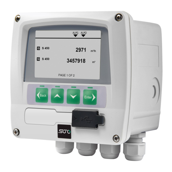
1. Safety instructions • Avoid direct UV and solar radiation during storage. • For the storage the humidity has to be <90%, no condensation. 2. Application The S 320 display can display all relevant parameters (flow, dew point, pressure, temperature, power consumption, compressor status etc.) in a compressed air system. -
Page 7: Technical Data
4. Technical Data 4. Technical Data 4.1 General Operating temperature 0°C... 50°C Housing material Protection class IP65 Dimensions See dimensional drawing on the next page Display Graphic display, 220 x 140 pixels with back light Interface USB to PC Keyboard 4 keys Weight 0.52 kg... -
Page 8: Dimensional Drawing
5. Dimensional drawing 5. Dimensional drawing S 320... -
Page 9: Installation
6. Installation 6. Installation Please make sure that all components listed below are included in your package. Qty Description Item No. S 320 Panel with ordered options D500 0320 and if ordered with casing Instruction manual No P/N 6.1 Installation Requirements The instrument can either be mounted into a panel or if ordered with the optional wall casing on a wall. -
Page 10: Ac Power Supply And Alarm Connection (A1640)
6. Installation 6.2.1 AC Power supply and alarm connection (A1640) AC power connection: AC alarm connection: 6.2.2 DC Power supply and alarm connection (A1641) DC power connection: DC alarm connection: S 320... -
Page 11: Signals At Back Terminals
6. Installation 6.2.3 Signals at back terminals Terminal Pin Signal Description Positive sensor supply Negative sensor supply Digital communication signal from sensors 4... 20 mA signal from sensor Active pulse signal from flow sensor Negative signal connection to PLC Iout 4... -
Page 12: Connection Of The Following Sensors
6. Installation 6.2.4 Connection of the following sensors S 320 S 400 / S 450 / S 201 S 220 / S 215 Colour 420 / Terminal Pin Signal blue white brown black grey Iout Remark In case the 4... 20 mA signal of S 215 is to be looped to a PLC the connection in the next table should be used. -
Page 13: Configuration
6. Installation 3-wire connect the sensor S 320 S 212 Terminal Signal Colour +I of PLC blue 2 of S 217 white 1 of S 217 brown -I of PLC black lout A. Process voltage B. Process current C. loop powered 4... 20 input 0... -
Page 14: Operation
7. Configuration To change certain or all settings by the user, S 320 can be connected to the PC via the USB interface. After starting S4C all device settings are accessible. All settings are stored permanently inside of the S 320 and do not need to be entered again, unless the user wants some changes. -
Page 15: Sensor Setting
8. Operation • Use this key to alter or adjust the setting option or numbering. • Use this key to enter to submenu or next menu level of the current selected menu item. • To confirm the setting change or enable an option in all setting state. -
Page 16: Signal Input
9. Signal input 9. Signal input 9.1 Digital input The display has one sensor input for SUTO flow / dew point sensor. 9.2 Analog input The display has one analog input for SUTO pressure / temperature sensor or further sensors (0... 20 mA / 4... 20 mA / 0... 10 V). -
Page 17: Warranty
14. Warranty SUTO provides a warranty for this product of 24 months covering the material and workmanship under the stated operating conditions from the date of delivery. Please report any findings immediately and within the warranty time.
Need help?
Do you have a question about the S320 and is the answer not in the manual?
Questions and answers