
Related Manuals for DERBEE P-51 MUSTANG


Summary of Contents for DERBEE P-51 MUSTANG
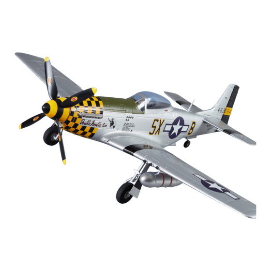
- Page 1 P-51 MUSTANG MANUAL / ANLEITUNG / MANUEL D‘INSTRUCTIONS ITEM NO. DB003PG / DB004PB...
-
Page 2: Safety Instructions
SAFETY INSTRUCTIONS WARNING: Read the entire assembly instructions to fa- miliarise yourself with the product functions and safety instructions before operation. As the user of this product, you are solely responsible for operation that does not endanger yourself or ot- THIS IS NOT A TOY! hers, or damage the product or property of others. -
Page 3: Specifications
DERBEE P-51D Mustang 75cm - Elevator blue DB003PG.4 DERBEE P-51D Mustang 75cm - Rudder blue DB003PG.5 DERBEE P-51D Mustang 75cm - Landing Gear blue DB003PG.6 DERBEE P-51D Mustang 75cm - Canopy blue DB003PG.7 DERBEE P-51D Mustang 75cm - Spinner blue DB004PB.1... - Page 4 ASSEMBLY OF THE LANDING GEAR To assemble the landing gear, you will need the wing, the two landing gear legs 2x screws 2*8mm and an appro- priate screwdriver. Insert the two landing gear legs into the receptacles pro- vided on the underside of the wing.
- Page 5 ASSEMBLY OF THE WINGS To assemble the wing, you will need the fuselage, wing, M4*45mm screw and an ap- propriate screwdriver. Insert the wing with the rear section into the correspon- ding receptacle on the un- derside of the fuselage and then place it on the front.
- Page 6 ASSEMBLY OF THE TAILS The fuselage, vertical stabili- zer, tailplane and a suitable glue are needed to assemble the tailplane. Insert the vertical stabilizer into the corresponding receptacle in the tailplane as shown and position it correctly. Note: Gluing the tailplane to the rudder is not intended! However, this can be done at your own discretion.
- Page 7 ASSEMBLY THE ANTENNA Connect the two linkage rods to the rudder horn of the rud- der and elevator as shown. Connect the attachment clips to the outermost holes of the control horns.
- Page 8 ASSEMBLY OF ADDITIONAL TANKS Attach the two auxiliary tanks to the designated positions on the underside of the wing using the adhesive strips al- ready attached. Ready assembled model.
-
Page 9: Rudder Deflections
ASSEMBLY FINISH Install the remaining RC components such as receiver and battery. Now the transmitter can be programmed. The rudder deflections and the center of gravity can be taken from the following tables. The values given are approximate values. RUDDER DEFLECTIONS Function Normal Ailerons... -
Page 10: Hinweise Zum Umweltschutz
SICHERHEITSHINWEISE WARNUNG: Lesen Sie die gesamte Montageanleitung, um sich vor dem Betrieb mit den Produktfunktionen und Sicherheitshinweisen vertraut zu machen. Als Benutzer dieses Produkts sind ausschließlich Sie für einen Betrieb verantwortlich, der weder Sie selbst DIES IST KEIN SPIELZEUG! noch andere gefährdet, bzw. der weder das Produkt Nicht für Kinder unter 14 Jahren. -
Page 11: Spezifikationen
4x 9g Fernsteuerung 6 Kanäle + ERSATZTEILE Art. Nr. Bezeichnung DB003PG.1 DERBEE P-51D Mustang 75cm - Rumpf blau DB003PG.2 DERBEE P-51D Mustang 75cm - Tragflächen blau DB003PG.3 DERBEE P-51D Mustang 75cm - Höhenruder blau DB003PG.4 DERBEE P-51D Mustang 75cm - Seitenruder blau DB003PG.5... -
Page 12: Montage Des Fahrwerks
MONTAGE DES FAHRWERKS Für die Montage des Fahr- werks werden die Tragfläche, die beiden Fahrwerksbeine, 2x Schrauben 2*8mm, sowie ein entsprechender Schrau- bendreher benötigt. Die beiden Fahrwerksbeine in die vorgesehenen Auf- nahmen auf der Tragflächen- unterseite stecken. Beide Fahrwerksbeine mit den entsprechenden Schrau- ben gegen Herausrutschen sichern. -
Page 13: Montage Der Tragfläche
MONTAGE DER TRAGFLÄCHE Für die Montage der Tragflä- che werden der Rumpf, Trag- fläche, Schraube M4*45mm sowie ein entsprechender Schraubendreher benötigt. Die Tragfläche mit dem hinteren Bereich in die ent- sprechende Aufnahme auf der Rumpfunterseite stecken und dann vorne auflegen. Die Tragfläche mit der ent- sprechenden Schraube am Rumpf befestigen. - Page 14 MONTAGE DER LEITWERKE Für die Montage der Leitwer- ke werden der Rumpf, Sei- tenleitwerk, Höhenleitwerk sowie ein geeigneter Kleber benötigt. Das Seitenleitwerk wie abgebildet in die entspre- chende Aufnahme im Höhenleitwerk einstecken und richtig positionieren. Hinweis: Eine Verklebung des Höhenleitwerks mit dem Seitenleitwerk ist nicht vorgesehen! Dieses kann aber nach eigenem Ermessen vorgenommen werden.
-
Page 15: Montage Der Antenne
MONTAGE DER ANTENNE Für die Montage der Antenne wird ein geeigneter Kleber benötigt. Die Antenne in die vorgesehene Position am Rumpf einkleben. - Page 16 MONTAGE DER ZUSATZTANKS Die beiden Zusatztanks mit Hilfe der bereits angebrach- ten Klebestreifen an den vorgesehenen Positionen auf der Tragflächenunterseite be- festigen. Fertig montiertes Modell.
- Page 17 MONTAGEABSCHLUSS Die noch übrigen RC Komponenten wie Empfänger und Akku einbauen. Nun kann der Sen- der programmiert werden. Die Ruderausschläge und der Schwerpunkt können den nach- stehenden Tabellen entnommen werden. Bei den angegebenen Werten handelt es sich um Richtwerte. RUDERAUSSCHLÄGE Funktion Normal Querruder...
-
Page 18: Consignes De Sécurité
CONSIGNES DE SÉCURITÉ ATTENTION : Merci de lire intégralement les instruc- tions de montage et les consignes de sécurité avant utilisation, afin de vous familiariser avec les fonction- nalités du produit. En tant qu’utilisateur du produit, vous êtes seul responsable d’une utilisation qui ne CECI N‘EST PAS UN JOUET ! vous mette pas en danger, ni vous, ni les autres, ou des Non destiné... -
Page 19: Caractéristiques
DERBEE P-51D Mustang 75cm - Cône d’hélice jaune DB0045PGB.9 DERBEE P-51D Mustang 75cm - Hélice DB0045PGB.10 DERBEE P-51D Mustang 75cm - 2 x réservoirs d’essence DB0045PGB.11 DERBEE P-51D Mustang 75cm - Jeu de tringleries DB0056PGB.14 DERBEE Contrôleur Brushless 20 A DB0056PGB.12... -
Page 20: Montage Du Train D'atterrissage
MONTAGE DU TRAIN D’ATTERRISSAGE Pour monter le train d’atter- rissage, il vous faut l’aile, les deux jambes de train, deux vis 2 x 8 mm et un tournevis adapté. Insérez les deux jambes de train dans les logements pré- sents sous les ailes. Fixez les deux jambes de train avec les vis adaptées pour éviter qu’elles puissent... -
Page 21: Montage Des Ailes
MONTAGE DES AILES Pour monter l’aile, il vous faut le fuselage, l’aile, une vis M4x45mm et le tournevis adapté. Insérer l’aile en logeant la partie arrière dans le récep- tacle correspondant sous le fuselage, puis mettez en place la partie avant. Fixez l’aile au fuselage à... - Page 22 MONTAGE DES EMPENNAGES Pour monter les empenna- ges, il vous faut le fuselage, le stabilisateur horizontal, la dérive et une colle adaptée. Insérez la dérive dans le logement correspondant du stabilisateur horizontal, comme montré, et posi- tionnez-le correctement. Note : Il n’est pas prévu de coller la dérive dans le stabilisateur ! Toutefois, vous pouvez le faire si c’est votre choix.
-
Page 23: Montage De L'antenne
MONTAGE DE L’ANTENNE Collez l’antenne factice dans son logement sur le dos du fuselage comme montré à l’aide d’une colle adaptée. - Page 24 MONTAGE DES RÉSERVOIRS SUPPLÉMENTAIRES Fixez les deux réservoirs au- xiliaires aux emplacements indiqués à l’intrados des ailes à l’aide du ruban adhésif dou- ble face déjà fixé aux réservo- irs. Le modèle est assemblé et prêt.
- Page 25 EQUIPEMENT FINAL Installez les éléments restant de la radiocommande comme le récepteur, ainsi que la batte- rie. Il faut maintenant programmer l’émetteur. Les débattements des gouvernes et la posi- tion du centre de gravité peuvent être ceux des tableaux qui suivent. Les valeurs indiquées sont approximatives.
- Page 26 NOTICE / NOTIZEN / NOTES...
- Page 27 NOTICE / NOTIZEN / NOTES...
- Page 28 DERBEE GERMANY DERBEE BELGIUM D-Power Modellbau Beez2B sprl Horst Derkum rue de Thy 54 Sürther Str. 92-94 B-1470 Baisy-Thy 50996 Köln, Germany Belgium info@d-power-modellbau.com info@beez2b.com +49 221 346 641 57 +32 23 76 71 82 www.d-power-modellbau.com www.beez2b.com © 2023 DERBEE...
Need help?
Do you have a question about the P-51 MUSTANG and is the answer not in the manual?
Questions and answers