Table of Contents
Advertisement
Quick Links
Advertisement
Table of Contents

Subscribe to Our Youtube Channel
Related Manuals for Freetech P8F153GVT-e


Summary of Contents for Freetech P8F153GVT-e
- Page 1 P8F153GVT-e MOTHER BOARD USER’S MANUAL Ver 2. NOV.26.2003...
- Page 3 Copyright Notice ©Copyright 2000 The information contained in this user’s manual and all accompanying documentation is copyrighted and all rights are reserved. This publication may not, in whole or in part, be reproduced, transcribed, stored in a retrieval system, translated into any language or computer language, or transmitted in any form whatsoever without the prior written consent from the manufacturer, except for copies retained by the purchasers for their personal...
- Page 4 Perface Using This Manual This manual is designed to help you build a reliable Personal Computer based on the P8F153GVT-e platform. Chapter 1—Quick Reference This chapter is for advanced users who want to quickly assemble a system. The mainboard layout along with jumper and switch settings, and memory configuration are provided.
-
Page 5: Table Of Contents
Perface Table of Contents 1. P8F153GVT-e QUICK REFERENCE ......1.1. Mainboard Layout ............ 1.2. I/O Ports ..............1.3. Front Panel Connector ..........1.4. Jumpers ..............1.5. PCI Frequency Settings ........... 1.6. Memory Installation ..........1.7. Connectors............... 1.8. Remote Controller ............ - Page 6 Perface 3.5.1. Front Panel Connectors (JP5) ........3.5.2. Audio CD-In Connector (CD1)........ 3.5.3. Audio AUX-IN Connector (AUX1)......3.5.4. Infrared (IR) Connector (IR)........3.5.5. LAN/Modem Wake up connectors (WOL)....3.5.6. Front USB Header (USB2) ........3.5.7. Floppy Drive Header (FDC) ........3.5.8.
- Page 7 Perface 4.3. System Information ..........4.4. General Configuration ..........4.5. Advanced Configuration........... 4.6. etBIOS Configuration ..........4.7. Primary / Secondary IDE Drivers ......4.8. Peripherals ............... 4.9. Power Management ........... 4.10. PCI & PnP ..............4.11. Hardware Monitor............. 4.12. Restore Manufacturer Settings ........ 4.13.
- Page 8 Perface 5.3.2.13. Eject ..............5.3.2.14. Exit..............5.3.2.15. Step Frame ............ 5.3.3. Exclusive CD/MP3 Controls........5.3.3.1 Shuffle ............. 5.3.4. Exclusive VCD Controls.......... 5.3.4.1 Audio Channel Select ........5.3.5. Exclusive DVD Controls ......... 5.3.5.1. Using the Menu..........5.3.5.2. Displaying Subtitles........5.3.5.3. Switching Language (Audio Streams) .... 5.3.5.4.
- Page 9 Perface 5.6.3. Navigational Support ..........5.6.4. DVD Support ............. 6. DRIVER AND UTILITY..........6.1. Flash Utility............... CD Driver Overview ..........6.2.1. Intel Chipset 845 INF Driver ........6.2.2. Intel Chipset 845 Busmaster IDE Driver ....6.2.3. ALC650 Audio Driver ..........6.2.4.
-
Page 11: P8F153Gvt-E Quick Reference
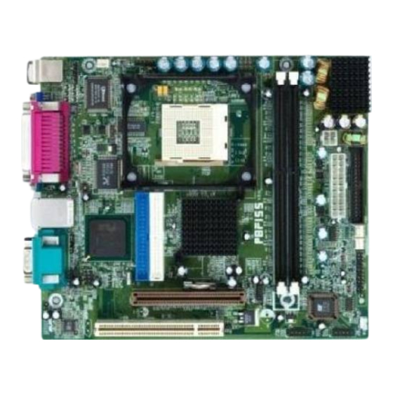
1. P8F153GVT-e Quick Reference This section is for users to get started using the mainboard straight away. 1.1. Mainboard Layout mPGA478B CPU socket (PGA478) Front Mic-IN, Line-IN Connector (JP9) ATX power connector (PW) Front Line-OUT Connector (JP8) ATX 12V power connector (PW1) -
Page 12: I/O Ports
Mainboard User’s Manual 1.2. I/O Ports 1.3. Front Panel Connector The following illustration shows the front panel connector pin assignments: I/O Port... -
Page 13: Jumpers
P8F153 Quick Reference 1.4. Jumpers Auto 100MHz FSB (CPU FSB) Empty 133MHz FSB Normal Mode (CMOS Clear) Clear CMOS 1.5. PCI Frequency Setting The PCI frequency settings are automatically set by the system 1.6. Memory Installation Note: This mainboard supports up to two double-sided or two single-sided DIMMs when the DDR DRAM interface is operating at 133 MHz. -
Page 14: Connectors
Mainboard User’s Manual 1.7. Connectors External Mouse / Keyboard : This 6-pin header is used for connecting mouse or keyboard. CPU FAN : This 3-pin header is used for connecting a CPU fan. COM2 Connector Chipset FAN System FAN Front Line-OUT Connector Front Mic-IN, Line-IN Connector Auxiliary-IN connector : This 4-pin header is an AUX1... -
Page 15: Introduction
2. Introduction 2.1. Overview The high quality P8F153GVT-e is a high-performance, enhanced function mainboard that supports mPGA478 Intel ® Pentium ® 4 processors that support a 533 MHz front side bus (FSB). This mainboard is designed around the latest and fastest Intel 845G/GE/GL/GV chipset in a standard ATX form factor. -
Page 16: Mainboard Specifications And Features
Mainboard User’s Manual 2.2. Mainboard Specifications and Features 2.2.1. Hardware Intel ® Pentium ® 4 processors in a 478-pin package, compatible Auto-detection CPU Onboard Voltage Regulator Module Provides 1.05V to 1.825V operating voltage Coprocessor CPU has built-in floating point unit Speed System bus clock 100 MHz PCI bus clock 33 MHz... - Page 17 Introduction Enhanced I/O One floppy disk controller One Standard/EPP/ECP parallel port connector Two 16550 compatible serial port connectors Two USB (Universal Serial Bus) ports One audio port connector, include line-out, line-in, mic-in, and midi/game ports I/O Options One connector for front panel USB ports 3/4 One IrDA compatible infrared (IR) connector Mouse PS/2 mouse connector...
-
Page 18: Software
Mainboard User’s Manual 2.2.2. Software BIOS AWARD AGP/PCI BIOS 2M-bit Flash BIOS with ESCD (Extended System Configuration Data) block Supports APM, Plug and Play, Multi-Boot, DMI and EIDE devices Supports ACPI Supports high-capacity LS-120 and ZIP removable media drive Driver and IDE Bus mastering Ultra DMA driver Utility AC97 codec audio driver... -
Page 19: Mainboard Layout
Introduction 2.3. Mainboard Layout Note: Because of optional items and design changes, your mainboard may not be identical to the one shown in the illustration. Mainboard Layout... - Page 20 Mainboard User’s Manual Key to Mainboard Components Name Function PGA478 CPU socket ATX standard power connector ATX 12V power connector DIMM1~2 DDR SDRAM Memory module slots IDE1 IDE 1 connector IDE2 IDE 2 connector Floppy drive connector 32-bit PCI Slot Front Panel Connector USB2 Front USB Connector...
-
Page 21: Microprocessor
Introduction 2.4. Microprocessor The mainboard is designed to operate with the following processor: Processor Type Speed Intel Pentium 4 800MHz~2.4GMHz+ 400, 533 MHz An onboard switching voltage regulator provides the required 1.05 to 1.825 volts for the processor. The processor sends five VID (Voltage identification) signals to the switching voltage regulator. -
Page 22: Chipset
Mainboard User’s Manual 2.7. Chipset The P8F153GVT-e supports the Intel 845G/GE/GL/GV chipset is designed for use in a desktop system based on an Intel® Pentium® 4 processor in a 478-pin package. The Intel 845G/GE/GL/GV chipset supports the Pentium 4 processor with 256-KB L2 cache and the Pentium 4 processor with 512-KB L2 cache on 0.13 micron process. - Page 23 Introduction AC97 (ALC650) two channels of audio. Dual Ultra ATA/100 controllers support faster IDE transfers to storage devices. This concludes Chapter 2. Chapter 3. covers hardware installation. Chipset...
-
Page 24: Hardware Installation
One S-Video One TV-out One LAN / Modem One set of loudspeakers 3.1. Unpacking The P8F153GVT-e mainboard package contains the following items: One mainboard One IDE 66/100 40-pin ribbon cable One floppy 34-pin ribbon cable Driver and utility CD User’s manual After removing the mainboard from its anti-static bag, place it on a grounded or antistatic surface (component side up). -
Page 25: Installation
Hardware Installation 3.2. Installation The P8F153GVT-e is designed to fit into a standard Mini Flex ATX form factor chassis. The pattern of the mounting holes and the position of the back panel connectors meet the Mini Flex ATX system board specification. The chassis comes with various mounting fasteners, which are made of metal or plastic. -
Page 26: Connector/Jumper Location
Mainboard User’s Manual 3.4. Connector/Jumper Location Connector/Jumper Location... -
Page 27: Attaching Connectors
Hardware Installation 3.5. Attaching Connectors 3.5.1. Front Panel Connectors (JP5) There are seven connectors on the mainboard for speaker, switches, and indicator lights on the system’s front panel. PW SW This 2-pin connector connects to the case-mounted Power button. RESET This 2-pin connector connects to the case-mounted reset switch and is used to reboot the system. -
Page 28: Audio Cd-In Connector (Cd1)
Mainboard User’s Manual 3.5.2. Audio CD-In Connector (CD1) This connector enables you to connect a CD-ROM to the mainboard and receive stereo audio input. 3.5.3. Audio AUX-IN Connectors (AUX1) This connector enables you to connect a stereo audio input from CD-ROM, TV-tuner, or MPEG card. -
Page 29: Infrared (Ir) Connector (Ir)
Hardware Installation 3.5.4. Infrared (IR) Connector (IR) This 5-pinheader connects to an optional wireless transmitting and receiving infrared module via a cable and a bracket. Configure BIOS to enable the IrDA port if you attach an infrared module to this connector. -
Page 30: Front Usb Header (Usb2)
Mainboard User’s Manual 3.5.6. Front USB Header (USB2) The mainborad provides one onboard 10-pin of dual USB port (port 3 and port 4) header. The header on the same signal with USB port 1 and port 2 on the back panel. 3.5.7. -
Page 31: Ide Connectors
Hardware Installation 3.5.8. IDE Connectors An IDE drive ribbon cable has two connectors to support two IDE drives. If a ribbon cable connects to two IDE drives at the same time, one of them has to be configured as Master and the other has to be configured as Slave by setting the drive select jumpers on the drive. -
Page 32: Back Panel Connectors
Mainboard User’s Manual 3.5.9. Back Panel Connectors The back panel provides external access to PS/2 style keyboard and mouse connectors, two serial ports, one parallel port, dual USB ports, and audio Line-out, Line-in, Mic-in, game/midi ports which are integrated on the mainboard. The figures below show the location of the back panel I/O connectors. - Page 33 Hardware Installation VGA Port Connect an external monitor to the blue 15-pin VGA port. S-Video Port You can connect S-Video devices to S-Video port on the back panel. RCA Video (TV-Out) You can connect RCA Video devices to RCA Video port (TV-Out) on the back- panel.
- Page 34 Mainboard User’s Manual Universal Serial Bus Ports You can connect two USB devices or USB hubs to the USB ports. The USB ports provide a hardware interface for low-speed peripherals such as the keyboard, mouse, joystick, scanner, printer and telephony devices, and also support MPEG-1 and MPEG-2 digital video.
- Page 35 Hardware Installation Audio Line-Out Port You can connect various audio devices to this audio jacks. Connect headphones or powered speakers to the lime-colored lineout connector. Audio Line-In Port You can connect a tape player or another audio source to the light blue Line-in connector to record audio on your computer or to play audio through your computer’s sound chip and speakers.
-
Page 36: Power Supply Connector
Mainboard User’s Manual 3.5.10. Power Supply Connector (PW / PW1) The ATX power supply has a single lead connector with a clip on one side of the plastic housing. There is only one way to plug the lead into to ATX power connector. Press the lead connector down until the clip snaps into place and secures the lead onto the connector. -
Page 37: Cpu/Chipset/System Fan Power Supplies
Hardware Installation 3.5.11. CPU/Chipset/System Fan Power Supplies (JP2/JP6/JP7) There are three fan connectors on the mainboard for the cooling fans. The connectors support fans of 12VDC/500mAMP (six watt) or less. When the system goes into sleep state, fans should be shut down to eliminate audible noise and reduce power consumption. -
Page 38: Pci Connector (Pci)
Mainboard User’s Manual 3.5.12. PCI Connector (PCI) PCI connector is one of equipment interfaces that connects peripheral equipment and motherboard. Its transfer speed is faster than traditional ISA. PCI is the mainstream transfer interface for extra adopter. 3.5.13. Serial COM2 Connector (J3) The mainboard provides one onboard serial COM2 connector. -
Page 39: External Mouse / Keyboard (Jp1)
Hardware Installation 3.5.14. External Mouse / Keyboard (JP1) The mainboard provides one onboard 6-pin for external mouse or keyboard. The headers have the same signal with ps/2 mouse or ps/2 keyboard. 3.5.15. Front Mic-IN, Line-IN Connector (JP9) Connector a tape player or another audio source to the light blue Line-in connector to record audio on your computer or to play audio through your computer’s sound chip and speaker. -
Page 40: Front Line-Out Connector (Jp8)
Mainboard User’s Manual 3.5.16. Front Line-OUT Connector (JP8) Connector the cable attached to line-out connector on front panel. This header shared same signal with line-out back panel. Attaching Connectors... -
Page 41: Installing The Cpu
Hardware Installation 3.6. Installing the CPU 3.6.1. Before You Begin 1. Be sure that your processor kit includes the following items: One processor with the fan or heat sink attached One power cable (for CPU with cooling fan attached) 2. Place the mainboard on a workbench (not in a chassis). Be sure that the mainboard is empty (that is, no DIMMs, cables, or cards are installed) and that the holes for the fan or heat sink support pegs are empty. -
Page 42: Removing The Processor
Mainboard User’s Manual 3. Identify the pin-1 corner of the mPGA478. The pin-1 corner is on the same side as the locking lever, as shown in the illustration below. 4. Identify the pin-1 corner of the processor (the pin-1 corner on the processor has a beveled edge). -
Page 43: Installing System Memory
Hardware Installation 3.7. Installing System Memory Maximum system memory supported by the mainboard is 2GB. The mainboard has two DIMM Sockets. Memory can be installed using 184-pin DDR SDRAM DIMM memory modules. These are no jumper settings required for the memory size or type, which is automatically detected by the BIOS. -
Page 44: Setting Jumpers
Mainboard User’s Manual 3.8. Setting Jumpers Refer to the following illustration and instructions to set the jumpers on your mainboard. 3.8.1. CPU FSB Jumper (JP3) The 3-pin header is used for CPU FSB. You can set “Auto”, “100 MHz” or “133 MHz”. 3.8.2. -
Page 45: Auto Power On
Hardware Installation 3. Place the shunt back to pin 1 and pin 2 of JP4. 4. Power on the system. Solution B If the CPU clock setup is incorrect, you may not be able to boot up . In this case, follow these instructions: 1. -
Page 46: Etbios Configuration
4. etBIOS Configuration After the hardware configuration of the mainboard is finished, and the system hardware has been assembled, the system may be powered up. At this point, CMOS setup should be run to ensure that system information is correct. The mainboard employs the latest Award BIOS CMOS chip with support for Windows Plug and Play. -
Page 47: Entering Setup
BIOS Configuration This program should be executed under the following conditions: When changing the system configuration When a configuration error is detected by the system and you are prompted to make changes to the Setup program When resetting the system clock When setting the CPU clock speed so that it automatically runs either fast or slow When redefining the communication ports to prevent any con... - Page 48 Mainboard User’s Manual “Press DEL to enter SETUP” To access the Whizpro BIOS SETUP program, press the <DEL> key to display the “CMOS SETUP UTILITY” screen: These screens provide access to the utility’s various functions. Listed below are explanations of the keys displayed at the bottom of the screen: Function Selects the next or previous menu or item in the selected...
-
Page 49: Setup Main Menu
BIOS Configuration 4.2. Setup Main Menu System Information Use this menu to display the basic system information. General Configuration Use this menu to enable and change the basic system configurations. Advanced Configuration Use this menu to enable and make changes to the advance features. -
Page 50: System Information
Mainboard User’s Manual 4.3. System Information Selecting “System Information”. Whizpro BIOS provide two system information screens. The first screen contains general system information and the second screen contains PCI device information. The information includes: 1. BIOS ID, BIOS revision, BIOS release date. 2. -
Page 51: General Configuration
BIOS Configuration 4.4. General Configuration Selecting “General Configuration” on the main program screen displays this menu: Date : Month, Day, Year Time : Hour, Minute, and Second. Use 24 Hour clock format (for PM numbers, add 12 to the hour, you would enter 4:30 p.m. As 16:30). - Page 52 Mainboard User’s Manual Power Up NumLock : The NumLock is on or off at power up. The default setting is “On” Power Up Floppy Seek : If this item is enabled, it checks the geometry of the floppy disk drives at start-up time. You don’t need to enable this item unless you have an old diskette drive with 360K capacity.
-
Page 53: Advanced Configuration
BIOS Configuration 4.5. Advanced Configuration Selecting “Advanced Configuration” on the main program screen displays this menu: IDE Devices Delay : Enable/Disable IDE drive delay. The options for the IDE Drive Delay time are: 2 sec, 5 sec, 10 sec, 15 sec, 20 sec, 25 sec and 30 sec. - Page 54 Mainboard User’s Manual Halt on POST Error : This setting determines which type of errors will cause the system to halt during boot up. The default setting is “Any Error” Video BIOS Cacheable : When enabled, BIOS will setup the chipset to cache video RAM area (A000 and B000 segment).
-
Page 55: Etbios Configuration
BIOS Configuration 4.6. etBIOS Configuration Selecting “etBIOS Configuration” on the main program screen displays this menu: Boot From etBIOS : Enable / Disable the first boot format BIOS. If you choose “Enabled”, please go checking chapter 5. Count Down to Boot OS : System exit count down timer in seconds. -
Page 56: Primary / Secondary Ide Drivers
Mainboard User’s Manual 4.7. Primary / Secondary IDE Drivers Selecting “Primary / Secondary IDE Drivers” on the main program screen displays this menu: User can manually or automatically set up different IDE hard drives in two separate IDE channels – primary and secondary IDE channels. - Page 57 BIOS Configuration Drive Mode : CHS : If the hard drive is the CHS mode. (Cylinder, Head, Sector) Auto : BIOS checks if the hard drive supports the LBA mode (Logical Block Addressing). If it is yes, LBA mode is enabled.
-
Page 58: Peripherals
Mainboard User’s Manual 4.8. Peripherals Selecting “Peripherals” on the main program screen displays this menu: Floppy Controller : These options enable or disable the on board floppy controller. The default setting is “Enabled.” Primary / Secondary IDE : These options enable or disable the on board Primary / Secondary IDE. - Page 59 BIOS Configuration Mode : Provide the mode options of “Printer”, “Standard+SPP”, “SPP+ EPP1.9”, “SPP+EPP 1.7”, “ECP”, “ECP+EPP 1.9” or ECP+EPP1.7”. This field allows you to set the operation mode of the parallel port. If you set “ECP” allows the parallel port to operate in bi-directional DMA mode.
-
Page 60: Power Management
Mainboard User’s Manual 4.9. Power Management Selecting “Power Management” on the main program screen displays this menu: Power Management : If this menu item is set to “Disabled”, power management features will not function regardless of other field settings in this menu. Note : Operating system driver may be needed to perform power management functions. - Page 61 BIOS Configuration S3 Video Init : Perform VGA BIOS initialization during S3(STR) resume. Stand-by Timer : Enable / Disable standby mode or set the idle time for system to switch into standby mode. This field allows you to set “off”, “1 min”, “2 min”, “4 min”, “8 min”, “16 min”. Suspend Timer : Enable / Disable suspend mode or set the idle time for system to switch into suspend mode.
- Page 62 Mainboard User’s Manual Wake on PME : When enabled, BIOS will enable PCI peripheral drive PME signal to awaken the system. Wake on RTC Alarm : When set to “Enabled,” you may set the date (day of the month), hour, minute and second to turn on your system.
-
Page 63: Pci & Pnp
BIOS Configuration 4.10. PCI & PnP Selecting “PCI & PnP” on the main program screen displays this menu: PnP OS Installed: This field allows you to use a Plug-and-Play (PnP) operating system to configure the PCI bus slots instead of using the BIOS. -
Page 64: Hardware Monitor
Mainboard User’s Manual 4.11. Hardware Monitor Selecting “Hardware Monitor” on the main program screen displays this menu: Show the information of system’s VCore, Voltages, VDD, Internal Core, CPU Fan Rotation, System Fan Rotation, and CPU Temperature. Press <ESC> to go back to the main screen PCI &... -
Page 65: Restore Manufacturer Settings
BIOS Configuration 4.12. Restore Manufacturer Settings Selecting “Restore Manufacturer Settings” on the main program screen displays this menu: Restore Manufacture Settings: This option allows you to load the default values for each of the parameters in the SETUP menus. When this option is selected, a confirmation is requested. -
Page 66: Exit
Mainboard User’s Manual 4.13. Exit Once you have made all your selections from the SETUP program, you should save your changes and exit SETUP. Select “Exit” from the main menu and the following dialog window appears: “ Save CMOS and “Exit”, “Discard Changes and Exit”, “Back to SETUP”. Save CMOS and Exit : Once you finish making your selections, select [Save CMOS and Exit] from dialog to ensure the values you selected has been saved to the CMOS... -
Page 67: Etdvd Guide
5. etDVD Guide BIOS Configuration 5.1. Starting etDVD During boot-up, hit the DEL key to enter the BIOS setup menu. Once in the setup menu, select the etBIOS Configuration sub-menu. Set [Boot from etBIOS] to [Enabled]. Now, etDVD will be launched every time the user turns on or reboots the PC. -
Page 68: Main Screen
Mainboard User’s Manual 5.2. Main Screen After etDVD is launched, the main screen will appear on the screen. On the right-hand side of the screen, there are five options available: CD/MP3, VCD, DVD, TV Tuner and Power. The functionality of each option is explained on the diagram below. -
Page 69: Using The Etdvd Player
etBIOS 5.3. Using the etDVD Player 5.3.1. The etDVD Interface A Once a player is selected, the player GUI will load. With the exception of the TV Tuner, each of the players shares the interface shown below. etDVD can also be controlled through a set of hotkeys. See chapter 6 for the hotkey reference tables. -
Page 70: General Control
Mainboard User’s Manual 5.3.2. General Control 5.3.2.1. Play Mode Click on the Player Mode Selector to cycle through the CD, VCD, and DVD player modes. 5.3.2.2. Drive Select The optical IDE drives in your system are mapped starting from 1 and their sequence is the same as the IDE sequence. -
Page 71: Pause
etBIOS 5.3.2.4. Pause Click on the Pause button to temporarily stop playing the media. Click on it again to resume playing the media. Or click on the Play button to resume. 5.3.2.5. Stop Click on the Stop button to stop playing the media. -
Page 72: Backward
Mainboard User’s Manual 5.3.2.7. Backward When a CD is in the optical drive, clicking on the Backward button will make the player skip backward 5% of the total playtime. When a VCD or DVD is in the optical drive, clicking on the Backward button will make the player increase the scan speed. -
Page 73: Progress Indicator
etBIOS 5.3.2.10. Progress Indicator The Progress Indicator shows the playback progress. During playback, simply drag the position marker on the progress indicator to play content at different progress points in the current media file. 5.3.2.11. Volume To adjust the volume, click directly on the color bar and slide it up and down. -
Page 74: Exit
Mainboard User’s Manual 5.3.2.14. Exit Click on the Exit button to return to the main screen. 5.3.2.15. Step Frame etDVD also has a Step Frame ability. Step Frame is only available in VCD and DVD player modes. It allows you to view video content frame by frame. 1. -
Page 75: Exclusive Cd/Mp3 Controls
etBIOS 5.3.3. Exclusive CD/MP3 Controls 5.3.3.1. Shuffle Click on the Shuffle button to make the CD/MP3 player randomly select tracks while playing. 5.3.4. Exclusive VCD Controls 5.3.4.1. Audio Channel Select Click on the Audio Output Channel button to select channel 1, channel 2, or both channels. -
Page 76: Displaying Subtitles
Mainboard User’s Manual 5.3.5.2. Displaying Subtitles Subtitles are supplied for practically all DVD titles. The language of the subtitles depends on the DVD region of your title. The subtitles function available only during playback. To disable or select the next available subtitles, click the SUBTITLES button accordingly. -
Page 77: Region Setup
etBIOS 5.3.5.5. Region Setup Most DVD discs and DVD drives contain a region code. A DVD disc can only be played when its region code matches the DVD drive's region code. If the etDVD player detects a mismatched region code between the disc and drive, the "Region Setup" pop-up window is presented. -
Page 78: Tv Tuner (Optional)
Mainboard User’s Manual 5.4. TV Tuner (Optional) etDVD also has TV Tuner functions. However, this set of functions is optional and may not have been included in your mainboard’s BIOS. In order to use the TV Tuner functions, you will need a compatible TV Tuner Card (see section 5.4.1.4). -
Page 79: Audio Input Options
etBIOS 5.4.1. Audio Input Options 5.4.1.1. Line-In As described in the TV Tuner section, the standard audio connection connects the Audio Out from the TV Tuner Card to the LINE-IN of the sound card. After starting the TV Tuner Card application, press the OSD key on the Remote Control (or F2 on the keyboard) to advance to the AUDIO IN sub-menu. -
Page 80: Validated Tv Tuner Cards
Mainboard User’s Manual 5.4.1.3. TV The Audio Out from the TV Tuner Card is passed through the PCI bus to the sound card. After starting the TV Tuner Card application, press the OSD key on the Remote Control (or F2 on the keyboard) to advance to the AUDIO IN sub-menu. -
Page 81: Function Reference
etBIOS 5.5. Function Reference 5.5.1. System Keys The user can press any of the system keys at anytime while in etDVD to activate its functionality. The following table explains the keys and functionalities. SYSTEM KEYS DESCRIPTION Wake Up Power on/off the system Sleep, Power, Pause/Break Power off the system 5.5.2. - Page 82 Mainboard User’s Manual BUTTON HOT KETS DESCRIPTION Stop F4 or s Stop playback Jump to the previous track/chapter Previous F5 or v if available Backward F6 or b Play backward if possible Forward F7 or f Play forward if possible Jump to the next track/chapter if Next F8 or n...
-
Page 83: Audio Cd/Mp3
etBIOS 5.5.3. Audio CD/MP3 BUTTON HOT KETS DESCRIPTION Shuffle F10 or u Toggles shuffle on or off Set repeat mode to: No repeat, Repeat F11 or r repeat current track, or repeat whole disc Turn on the screen saver by z or Z Screen Saver turning off the monitor... -
Page 84: Dvd
Mainboard User’s Manual 5.5.5. BUTTON HOT KETS DESCRIPTION Jump to the menu screen if Menu F10 or [ available Resume movie playback from a Resume F11 or ] previous point in the movie, before “Menu” was selected Change to the next available Subtitle screen subtitle Change to the next available audio... -
Page 85: Tv Tuner
etBIOS 5.5.7. TV Tuner REMOTE HOT KETS DESCRIPTION Channel+ Next Channel Channel- Shift + Tab Previous Channel Select Menu Item for Adjustment : Brightness / Contrast / Color Hue / Color U / Color V / MTS / AUDIO-IN / Channels Search F3 or Space Auto-search for channels Tune reception frequency in tiny... - Page 86 Mainboard User’s Manual BUTTON HOT KETS DESCRIPTION Enter Select Channel Number entered from the Numeric Keypad. Enter Enter Otherwise Advance to Next Channel Display Display channel ID Exit TV tuner Used to enter channel number. Num keys Num keys The user can either wait 1 second or press Enter to select the channel Increase audio volume Decrease audio volume...
-
Page 87: Specification
etBIOS 5.6. Specification 5.6.1. Video Supports DVD (MPEG-2) Supports VCD version 1.0 format (MPEG-1) 5.6.2. Audio Supports A/52 audio decoding Supports MPEG-2 audio and LPCM (Linear Pulse Code Modulation) decoding 5.6.3. Navigational Support Play bar slider control allows instantaneous access to any scene Fast forward speeds of 2X, 4X, 8X (16X and 32X for VCD) Fast backward speeds of 2X, 4X, 8X (16X and 32X for VCD) Frame by frame stepping in forward (and backward VCD) direction(s) -
Page 88: Driver And Utility
6. Driver and Utility 6.1 Flash Utility The BIOS of the P8F153GVT-e mainboard can be upgraded by using a Flash utility. A new version of the BIOS can be downloaded from the factory’s BBS and Web site. The system BIOS is stored in a 2 M-bit Flash EEPROM that can be erased and reprogrammed by the Flash utility. -
Page 89: Cd Driver Overview
CD. The support CD has an easy to use menu that enables you to automatically install the drivers and software that you want. The P8F153GVT-e CD include 1. Install Mainboard Software (Intel 845G/GE/GL/GV) 2. Install Audio Device Software (ALC) 3. -
Page 90: Intel Chipset 845 Inf Driver
Mainboard User’s Manual 6.2.1. Intel chipset 845 INF driver This folder has chipset 845 INF drivers for WIN 95 / 98 / ME / NT / 2000 / XP. The Installation Steps: 1. Insert the manufacturer CD-ROM into your CD-ROM drive. 2. -
Page 91: Alc650 Audio Driver
Driver and Utility 6.2.3. ALC650 Audio Driver Software and drivers are provided for the 82801DB codec sound system that is integrated on this mainboard. The 82801DB codec allows the system to generate optimal sound effects. Drivers are provided for Windows 95 / 98 / ME / NT / 2000 / XP. The manual Installation Steps: 1. -
Page 92: Online Services
Mainboard User’s Manual 6.3. Online Services Flexus Computer Technology, under the Freetech brand name, has consistently won recognition for excellence in the design and manufacturing of high quality mainboards! Our products are globally recognized among the leading cost-performance mainboards in the industry today and we are a...
Need help?
Do you have a question about the P8F153GVT-e and is the answer not in the manual?
Questions and answers