Table of Contents
Advertisement
Quick Links
Advertisement
Table of Contents

Related Manuals for Freetech P8F150


Summary of Contents for Freetech P8F150
- Page 1 P P P P 8 8 8 8 F1 F1 F1 F150 MOTHER BOARD USER’S MANUAL...
- Page 2 Copyright Notice ©Copyright 2000 The information contained in this user’s manual and all accompanying documentation is copyrighted and all rights are reserved. This publication may not, in whole or in part, be reproduced, transcribed, stored in a retrieval system, translated into any language or computer language, or transmitted in any form whatsoever without the prior written consent from the manufacturer, except for copies retained by the purchasers for their personal...
- Page 3 Perface Using This Manual This manual is designed to help you build a reliable Personal Computer based on the P8F150 platform. Chapter 1—Quick Reference This chapter is for advanced users who want to quickly assemble a system. The mainboard layout along with jumper and switch settings, and memory configuration are provided.
-
Page 4: Table Of Contents
Perface Table of Contents 1. P8F150 QUICK REFERENCE........1.1. Mainboard Layout............. 1.2. I/O Ports ..............1.3. Front Panel Connector ..........1.4. Jumpers..............1.5. PCI and AGP Frequency Settings......1.6. Memory Installation ..........1.7. Connectors ............... 2. INTRODUCTION ............. 2.1. Overview .............. - Page 5 Perface 3.5.1. Front Panel Connectors (JP6) ........3.5.2. Audio CD-In Connector (CD1) ........ 3.5.3. Audio AUX-IN Connector (AUX1) ......3.5.4. Infrared (IR) Connector (IR)........3.5.5. LAN/Modem Wake up connectors (WOL) ....3.5.6. Front USB Header (USB2~3)........3.5.7. Floppy Drive Header (FDC) ........3.5.8.
- Page 6 Perface 4.8. PC Health Status Option .......... 4.9. Frequency/Voltage Control........4.10 . Load Fail-Safe Defaults Option........ 4.11. Load Optimized Defaults Option ......4.12. Set Supervisor/User Password ........ 4.13. Save & Exit Setup ............ 4.14. Exit Without Saving ..........5. DRIVER AND UTILITY..........5.1.
-
Page 7: P8F150 Quick Reference
1. P8F150 Quick Reference This section is for users to get started using the mainboard straight away. 1.1. Mainboard Layout mPGA478B CPU socket (PGA478) LAN/Modem Wake up Connector(WOL) ATX power connector (PW2) Serial Connector(COM2) ATX 12V power connector (PW1) AUDIO connectors (AUX1) -
Page 8: I/O Ports
Mainboard User’s Manual 1.2. I/O Ports 1.3. Front Panel Connector The following illustration shows the front panel connector pin assignments: I/O Port... -
Page 9: Jumpers
P8F150 Quick Reference 1.4. Jumpers Auto 100MHz FSB (CPU FSB) Empty 133MHz FSB Normal Mode Clear CMOS (CMOS Clear) 1.5. PCI and AGP Frequency Setting The PCI and AGP frequency settings are automatically set by the system 1.6. Memory Installation... -
Page 10: Connectors
Mainboard User’s Manual 1.7. Connectors Chipset FAN System FAN Front Panel Connector TV-Out connector Auxiliary-IN connector : This 4-pin header is an AUX1 auxiliary input connector. CD-IN connector : This 4-pin header is used for connecting the CD ROM audio input to the sound card. -
Page 11: Introduction
2. Introduction 2.1. Overview The high quality P8F150 is a high-performance, enhanced function mainboard that supports mPGA478 Intel ® Pentium ® 4 processors that support a 533 MHz front side bus (FSB). This mainboard is designed around the latest and fastest Intel 845G/845GL chipset in a standard ATX form factor. -
Page 12: Mainboard Specifications And Features
Mainboard User’s Manual 2.2. Mainboard Specifications and Features 2.2.1. Hardware Intel ® Pentium ® 4 processors in a 478-pin package, compatible Auto-detection CPU Onboard Voltage Regulator Module Provides 1.05V to 1.825V operating voltage Coprocessor CPU has built-in floating point unit Speed System bus clock 100 MHz PCI bus clock 33 MHz... - Page 13 Introduction On-Board TV-Out TV-out with 1024×768 input video resolution Chrontel CH7012A Enhanced I/O One floppy disk controller One Standard/EPP/ECP parallel port connector Two 16550 compatible serial port connectors Two USB (Universal Serial Bus) ports One audio port connector, include line-out, line-in, mic-in, and midi/game ports I/O Options Two connector for front panel USB ports 3/4,...
-
Page 14: Software
Mainboard User’s Manual 2.2.2. Software BIOS AWARD AGP/PCI BIOS 2M-bit Flash BIOS with ESCD (Extended System Configuration Data) block Supports APM, Plug and Play, Multi-Boot, DMI and EIDE devices Supports ACPI Supports high-capacity LS-120 and ZIP removable media drive Driver and IDE Bus mastering Ultra DMA driver Utility AC97 codec audio driver... -
Page 15: Mainboard Layout
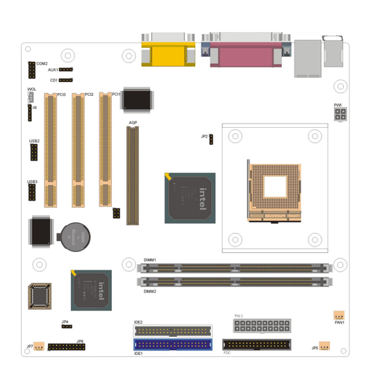
Introduction 2.3. Mainboard Layout Note: Because of optional items and design changes, your mainboard may not be identical to the one shown in the illustration. Mainboard Layout... - Page 16 Mainboard User’s Manual Key to Mainboard Components Name Function PGA478 CPU socket ATX standard power connector ATX 12V power connector DIMM1~2 DDR SDRAM Memory module slots IDE1 IDE 1 connector IDE2 IDE 2 connector Floppy drive connector PCI1~3 32-bit PCI Slot 4x AGP Slot Front Panel Connector USB2~3...
-
Page 17: Microprocessor
Introduction 2.4. Microprocessor The mainboard is designed to operate with the following processor: Processor Type Speed Intel Pentium 4 1.4~2.4GMHz+ 400, 533 MHz An onboard switching voltage regulator provides the required 1.05 to 1.825 volts for the processor. The processor sends five VID (Voltage identification) signals to the switching voltage regulator. -
Page 18: Chipset
Mainboard User’s Manual 2.7. Chipset The P8F150 supports the 845G chipset is designed for use in a desktop system based on an Intel® Pentium® 4 processor in a 478-pin package. The 845G chipset supports the Pentium 4 processor with 256-KB L2 cache and the Pentium 4 processor with 512-KB L2 cache on 0.13 micron process. -
Page 19: Raid
Introduction !" AC97 (ALC201A) two channels of audio. !" AC97(ALC650) 5.1 channels of audio.(optional) !" Dual Ultra ATA/100 controllers support faster IDE transfers to storage devices. This concludes Chapter 2. Chapter 3. covers hardware installation. Chipset... -
Page 20: Hardware Installation
!" One PS/2 keyboard !" One LAN / Modem !" One set of loudspeakers 3.1. Unpacking The P8F150 mainboard package contains the following items: !" One mainboard !" One IDE 66/100 40-pin ribbon cable !" One floppy 34-pin ribbon cable !"... -
Page 21: Installation
Hardware Installation 3.2. Installation The P8F150 is designed to fit into a standard Mini Flex ATX form factor chassis. The pattern of the mounting holes and the position of the back panel connectors meet the Mini Flex ATX system board specification. -
Page 22: Connector/Jumper Location
Mainboard User’s Manual 3.4. Connector/Jumper Location Connector/Jumper Location... -
Page 23: Attaching Connectors
Hardware Installation 3.5. Attaching Connectors 3.5.1. Front Panel Connectors (JP6) There are seven connectors on the mainboard for speaker, switches, and indicator lights on the system’s front panel. PW SW This 2-pin connector connects to the case-mounted Power button. RESET This 2-pin connector connects to the case-mounted reset switch and is used to reboot the system. -
Page 24: Audio Cd-In Connector (Cd1)
Mainboard User’s Manual 3.5.2. Audio CD-In Connector (CD1) This connector enables you to connect a CD-ROM to the mainboard and receive stereo audio input. 3.5.3. Audio AUX-IN Connectors (AUX1) This connector enables you to connect a stereo audio input from CD-ROM, TV-tuner, or MPEG card. -
Page 25: Infrared (Ir) Connector (Ir)
Hardware Installation 3.5.4. Infrared (IR) Connector (IR) This 5-pinheader connects to an optional wireless transmitting and receiving infrared module via a cable and a bracket. Configure BIOS to enable the IrDA port if you attach an infrared module to this connector. -
Page 26: Front Usb Header (Usb2~3)
Mainboard User’s Manual 3.5.6. Front USB Header (USB2~3) The mainborad provides one onboard 10-pin of dual USB port (port 3 and port 4) header. The header on the same signal with USB port 1 and port 2 on the back panel. 3.5.7. -
Page 27: Ide Connectors
Hardware Installation 3.5.8. IDE Connectors An IDE drive ribbon cable has two connectors to support two IDE drives. If a ribbon cable connects to two IDE drives at the same time, one of them has to be configured as Master and the other has to be configured as Slave by setting the drive select jumpers on the drive. -
Page 28: Back Panel Connectors
Mainboard User’s Manual 3.5.9. Back Panel Connectors The back panel provides external access to PS/2 style keyboard and mouse connectors, two serial ports, one parallel port, dual USB ports, and audio Line-out, Line-in, Mic-in, game/midi ports which are integrated on the mainboard. The figures below show the location of the back panel I/O connectors. - Page 29 Hardware Installation Universal Serial Bus Ports You can connect two USB devices or USB hubs to the USB ports. The USB ports provide a hardware interface for low-speed peripherals such as the keyboard, mouse, joystick, scanner, printer and telephony devices, and also support MPEG-1 and MPEG-2 digital video.
- Page 30 Mainboard User’s Manual Serial Port Connect a serial device such as a mouse or modem to the 9-pin serial port. You can set the serial port IRQs in BIOS. Refer to integrated Peripherals in Chapter 4 for details. Note: Serial printers must be connected to the serial port. VGA Port Connect an external monitor to the blue 15-pin VGA port.
- Page 31 Hardware Installation Audio Line-Out Port You can connect various audio devices to this audio jacks. Connect headphones or powered speakers to the lime-colored lineout connector. Audio Line-In Port You can connect a tape player or another audio source to the light blue Line-in connector to record audio on your computer or to play audio through your computer’s sound chip and speakers.
-
Page 32: Power Supply Connector
Mainboard User’s Manual 3.5.10. Power Supply Connector (PW1 / PW2) The ATX power supply has a single lead connector with a clip on one side of the plastic housing. There is only one way to plug the lead into to ATX power connector. Press the lead connector down until the clip snaps into place and secures the lead onto the connector. -
Page 33: Cpu/Chi
Hardware Installation 3.5.11. CPU/Chipset/System Fan Power Supplies (FAN1/JP5/JP7) There are three fan connectors on the mainboard for the cooling fans. The connectors support fans of 12VDC/500mAMP (six watt) or less. When the system goes into sleep state, fans should be shut down to eliminate audible noise and reduce power consumption. -
Page 34: Pci Connector (Pci1~3)
Mainboard User’s Manual 3.5.12. PCI Connector (PCI1~3) PCI connector is one of equipment interfaces that connects peripheral equipment and motherboard. Its transfer speed is faster than traditional ISA. PCI is the mainstream transfer interface for extra adopter. 3.5.13. Serial COM2 Connector (COM2) The mainboard provides one onboard serial COM2 connector. -
Page 35: Tv-Out Connector (J2)
Hardware Installation 3.5.14. TV-Out Connector (J2) The mainboard provides one onboard 6-pin for TV-Out connector. Attaching Connectors... -
Page 36: Installing The Cpu
Mainboard User’s Manual 3.6. Installing the CPU 3.6.1. Before You Begin Be sure that your processor kit includes the following items: !" One processor with the fan or heat sink attached !" One power cable (for CPU with cooling fan attached) Place the mainboard on a workbench (not in a chassis). -
Page 37: Removing The Processor
Hardware Installation 3. Identify the pin-1 corner of the mPGA478. The pin-1 corner is on the same side as the locking lever, as shown in the illustration below. 4. Identify the pin-1 corner of the processor (the pin-1 corner on the processor has a beveled edge). -
Page 38: Installing System Memory
Mainboard User’s Manual 3.7. Installing System Memory Maximum system memory supported by the mainboard is 2 GB. The mainboard has two DIMM Sockets. Memory can be installed using 184-pin DDR SDRAM DIMM memory modules. These are no jumper settings required for the memory size or type, which is automatically detected by the BIOS. -
Page 39: Setting Jumpers
Hardware Installation 3.8. Setting Jumpers Refer to the following illustration and instructions to set the jumpers on your mainboard. 3.8.1. CPU FSB Jumper (JP2) The 3-pin header is used for CPU FSB. You can set “Auto”, “100 MHz” or “133 MHz”. 3.8.2. -
Page 40: Auto Power On
Mainboard User’s Manual seconds. 3. Place the shunt back to pin 1 and pin 2 of JP4. 4. Power on the system. Solution B If the CPU clock setup is incorrect, you may not be able to boot up . In this case, follow these instructions: Turn the system off, then on again. -
Page 41: Bios Configuration
4. BIOS Configuration Hardware Installation After the hardware configuration of the mainboard is finished, and the system hardware has been assembled, the system may be powered up. At this point, CMOS setup should be run to ensure that system information is correct. -
Page 42: Entering Setup
Mainboard User’s Manual This program should be executed under the following conditions: " ! When changing the system configuration !" When a configuration error is detected by the system and you are prompted to make changes to the Setup program "... - Page 43 BIOS Configuration “Press DEL to enter SETUP” To access the AWARD BIOS SETUP program, press the <DEL> key to display the “CMOS SETUP UTILITY” screen: These screens provide access to the utility’s various functions. Listed below are explanations of the keys displayed at the bottom of the screen: Function Escape key: Exits the current menu...
-
Page 44: Standard Cmos Features
Mainboard User’s Manual 4.2. Standard CMOS Features Standard CMOS Features is the same for all three chipsets. Selecting “Standard CMOS Features” on the main program screen displays the following menu: The Standard CMOS Setup utility is similar for all three chipsets and is used to configure the following features: Date : Month, Day, Year Time : Hour, Minute, and Second. - Page 45 BIOS Configuration ! IDE HDD Auto-Detection : Press <Enter> while this item is highlighted if you want the Setup Utility to automatically detect and configure a hard disk drive on the IDE channel. If your system has an IDE hard drive, you can use this utility to detect its parameters and enter them into the Standard CMOS Setup automatically If the auto-detected parameters displayed do not match the ones...
- Page 46 Mainboard User’s Manual " ! "Access Mode : This item defines some special ways that can be used to access IDE hard disks such as LBA (Large Block Addressing). Leave this value at “Auto” and the system will automatically decide the fastest way to access the hard disk drive. Press <Esc>...
- Page 47 BIOS Configuration Halt On : This setting determines which type of errors will cause the system to halt during boot up. The options are: ! ! ! ! All Errors ! ! ! ! No Errors ! ! ! ! All, But Keyboard ! ! ! ! All, But Diskette ! ! ! ! All, But Disk/Key”.
-
Page 48: Advanced Bios Features
Mainboard User’s Manual 4.3. Advanced BIOS Features Selecting “Advanced BIOS Features” on the main program screen displays this menu, which allows you to define advanced information about your system. You can make modifications to most of these items without introducing fatal errors to your system. Note that the page has a scroll-bar to scroll down to more items. - Page 49 BIOS Configuration First/Second/Third Boot Device : Use these three items to select the priority and order of the devices that your system searches for an operating system at start-up time. The default settings are “Floppy”, “HDD-0”, or “LS120” respectively. Boot Other Device : If you enable this item, the system will search all other possible locations for an operating system if it fails to find one in the devices specified under the First, Second, and Third boot devices.
- Page 50 Mainboard User’s Manual !" Typematic Rate (Chars/Sec) : This setting controls the speed at which the system registers repeated keystrokes. The choices range from 6 to 30 Chars/Sec. The default setting is “6” Chars/Sec. !" Typematic Delay (Msec) : This setting controls the time between the display of the first and second characters.
- Page 51 BIOS Configuration Small Logo (EPA) Show : Enables and disables the EPA logo when booting up. The default setting is “Disabled”. After you have made your selections in the BIOS Features Setup screen, press <ESC> to go back to the main screen. Advanced BIOS Features...
-
Page 52: Advanced Chipset Features
Mainboard User’s Manual 4.4. Advanced Chipset Features Selecting “Advanced Chipset Features” on the main program screen displays this menu: This option displays a table of items that define critical timing parameters of the mainboard. You should leave the items on this page at their default values unless you are very familiar with the technical specification of your system hardware. - Page 53 BIOS Configuration Active to Precharge Delay : This item enables you to set the number of DRAM clocks for TRAS. TRAS indicates the time required for the memory to restore data and come to a full charge. The default setting is “7”. DRAM RAS# to CAS# Delay : Enables you to select the RAS to CAS delay time in HCLKs of 2/2 or 3/3.
- Page 54 Mainboard User’s Manual Memory Hole At 15M-16M : If Set to “Enabled”, when the system memory size is equal to or greater than 16M bytes, the physical memory address from 15M to 16M will be passed to PCI or ISA and there will be a 1 MB hole in your system memory.
-
Page 55: Integrated Peripherals
BIOS Configuration 4.5. Integrated Peripherals Selecting “Integrated Peripherals” on the main program screen displays field. On-Chip Primary/ Secondary PCI IDE : These options enable or disable the primary and secondary onboard IDE controllers. The default setting is “Enabled.” IDE Primary/Secondary Master/Slave PIO : Each IDE channel supports a master device and a salve device. - Page 56 Mainboard User’s Manual USB Controller : Enables the USB controller. Leave this at the default “Enabled” if you want to connect USB devices to your computer. USB Keyboard Support : Enables USB keyboard support for legacy operating systems. The default setting is “Disabled”. USB Mouse Support : Enabled this function when a USB mouse is used.
- Page 57 BIOS Configuration POWER ON Function : Enables you to set keyboard or mouse events, or a password to power on the computer. When set to “Password,” you must key in your password before pressing any keyboard key to start the computer. The password is set in the “KB Power ON Password”...
- Page 58 Mainboard User’s Manual Onboard Serial Port 1 : This option is used to assign the I/O address and address and interrupt request (IRQ) for onboard serial port 1 (COM1). Onboard Serial Port 2 : This option is used to assign the I/O address and address and interrupt request (IRQ) for onboard serial port 2 (COM2).
- Page 59 BIOS Configuration Use IR Pins : Use this item to set the IR pins. The options are “IR-Rx2Tx2”(default) and “RxD2, TxD2”. Onboard Parallel Port : This option is used to assign the I/O address for the onboard parallel port. The options are: ! 378 / IRQ7 (default) ! 278 / IRQ5 ! 3BC / IRQ7...
-
Page 60: Power Management Setup
Mainboard User’s Manual 4.6. Power Management Setup This option lets you control system power management. The system has various power-saving modes including powering down the hard disk, turning off the video, suspending to RAM, and software power down that allows the system to be automatically resumed by certain events. - Page 61 BIOS Configuration " " ACPI Suspend Type : Use this item to define how your system suspends. If set to S1(POS) (default), the suspend mode is equivalent to a software power down. If set to S3(STR), the suspend mode is a suspend to RAM the system shuts down with the exception of a refresh current to the system memory.
- Page 62 Mainboard User’s Manual " " MODEM Use IRQ : If you want an incoming call on a modem to automatically resume the system from a power-saving mode, use this item to specify the interrupt request line (IRQ) that is used by the modem.
- Page 63 BIOS Configuration " " Wake-Up by PCI card : This setting enables/disables PCI card wakeup for PCI spec2.2. The default is “Enabled.” " Power On by Ring : When set to “Enabled,” any activity on the Modem port will wake up the system from a power saving mode. The options are “Disabled”...
- Page 64 Mainboard User’s Manual Primary/Secondary IDE 0/1: When enabled, any activity on the primary or secondary IDE channels will wake up the system from a power saving mode. FDD, COM, LPT Port: When enabled, any activity on the floppy disk drive (FDD), serial ports (COM), or parallel ports (LPT) will wake up the system from a power saving mode.
-
Page 65: Pnp/Pci Configurations
BIOS Configuration 4.7. PnP/PCI Configuration This option displays a table of items that configures how PnP (Plug and Play) and PCI expansion cards operate in your in your system. Both the ISA and PCI buses on the Mainboard use system IRQs (Interrupt Requests) and DMAs (Direct Memory Access). - Page 66 Mainboard User’s Manual Resources Controlled By : The setting “Manual” allows you to control IRQs and DMAs individually. The other option is “Auto” which will detect the system resources and automatically assign the relative IRQs and DMAs for each peripheral. !"...
-
Page 67: Pc Health Status Option
BIOS Configuration 4.8. PC Health Status On mainboards the support hardware monitoring, this item lets you monitor the parameters for critical voltages, critical temperatures and fan speeds: Selecting “PC Health Status” on the main program screen displays this menu: CPU Warning Temperature : This feature enables you to set the warning temperature for CPU overheating. - Page 68 Mainboard User’s Manual • Current FAN3 Speed • Vcore (CPU Vcore Voltage) • Vcc3 (Onboard 3.3V) • + 5V • +12V (power supply’s +12 volt) • -12V (power supply’s -12 volt) • VBAT(V) (CMOS Battery Voltage) • 5VSB(V) (Standby 5V) Shutdown Temperature : Enables you to set the maximum temperature the system can reach before powering down.
-
Page 69: Frequency/Voltage Control
BIOS Configuration 4.9. Frequency/Voltage Control This item enables you to set the clock speed ad system bus for your system. The clock speed ad system bus is determined by the kind of processor you have installed in your system. CPU Clock Ratio : Use this item to select a multiplier for the system front side bus (FSB) frequency. - Page 70 Mainboard User’s Manual CPU Host/3V66/PCI Clock : This item appears if you have set the CPU Internal Core Speed to Manual. Use the CPU/PCI Clock to set the system bus frequency for the installed processor. The values for this field range from 100/66/33 MHz to 130/87/43 MHz After you have made your selections in the Frequency / Voltage Control Setup, press the <Esc>...
-
Page 71: Load Fail-Safe Defaults Option
BIOS Configuration 4.10. Load Fail-Safe Defaults Option This option opens a dialog box that lets you install fail-safe defaults for all appropriate items in the Setup Utility: Press <Y> and then <Enter> to install the defaults. Press <N> and then <Enter> to not install the defaults. The fail-safe defaults place no great demands on the system and are generally stable. -
Page 72: Save & Exit Setup
Mainboard User’s Manual Press <Enter> after entering the password. At the next prompt, confirm the new password by retyping it and pressing <Enter> again. To disable the password, press <Enter> instead of entering a new password when the “Enter Password” dialog box appears. A message appears confirming that the password has been disabled. -
Page 73: Driver And Utility
5. Driver and Utility 5.1 Flash Utility The BIOS of the P8F150 mainboard can be upgraded by using a Flash utility. A new version of the BIOS can be downloaded from the factory’s BBS and Web site. The system BIOS is stored in a 2 M-bit Flash EEPROM that can be erased and reprogrammed by the Flash utility. -
Page 74: Cd Driver Overview
CD. The support CD has an easy to use menu that enables you to automatically install the drivers and software that you want. The P8F150 CD include 1. Install Mainboard Software (Intel 845) 2. Install Audio Device Software (ALC) 3. -
Page 75: Intel Chipset 845 Inf Driver
Driver and Utility 5.2.1. Intel chipset 845 INF driver This folder has chipset 845 INF drivers for WIN 95 / 98 / ME / NT / 2000 / XP. The Installation Steps: 1. Insert the manufacturer CD-ROM into your CD-ROM drive. 2. -
Page 76: Alc201 Audio Driver
Mainboard User’s Manual 5.2.3. ALC201 Audio Driver Software and drivers are provided for the 82801DB codec sound system that is integrated on this mainboard. The 82801DB codec allows the system to generate optimal sound effects. Drivers are provided for Windows 95 / 98 / ME / NT / 2000 / XP. The manual Installation Steps: Insert the manufacturer CD-ROM into your PC CD-ROM drive. -
Page 77: Online Services
Driver and Utility 5.3. Online Services Flexus Computer Technology, under the Freetech brand name, has consistently won recognition for excellence in the design and manufacturing of high quality mainboards! Our products are globally recognized among the leading cost-performance mainboards in the industry today and we are a...
Need help?
Do you have a question about the P8F150 and is the answer not in the manual?
Questions and answers