
Related Manuals for Freetech P8F217 Series


Summary of Contents for Freetech P8F217 Series
- Page 1 P8F217 series User’s Manual Version 1.3 Date: 7/15/04 P8F217 series User’s Manual...
- Page 2 Trademark All trademarks are the property of their respective holders. Any question please visit our website at http://www.freetech.com. P8F217 series User’s Manual...
- Page 3 Hardware P8F217L Motherboard ............Cable Kit 40-pin ATA100 IDE Flat Cable.......... 34-pin Floppy Cable............Dual-USB Port Cable ............DB9 COM Port Cable............Audio Cable.……………………………………………………… I/O Shield………………………………………………………… Printed Matter and Software User’s Manual ..............Driver CD ................P8F217 series User’s Manual...
-
Page 4: Table Of Contents
Digital VGA Interface (P8F217L only) ......... 21 ............23 THERNET NTERFACE ..............24 UDIO NTERFACE 2.10 ............26 WITCH AND NDICATOR CHAPTER 3. BIOS SETUP ............... 28 CHAPTER 4 AUDIO CHANNEL CONFIGURATION......30 CHAPTER 5. DISPLAY SETTINGS........... 32 P8F217 series User’s Manual... - Page 5 FLASH THE BIOS............. 42 BIOS A ............42 LASH ..............42 LASH ETHOD APPENDIX C. SYSTEM RESOURCES..........44 I/O Port Address Map ............. 44 Memory Address Map ............45 System IRQ and DMA Resource .......... 46 ONLINE SERVICES………………………………...……………………...48 P8F217 series User’s Manual...
-
Page 6: Chapter 1. Introduction
Hi-Speed USB 2.0 and IEEE 1394 Interface Intel ICH4 built-in Hi-Speed USB 2.0 controller and onboard IEEE 1394 chipset let P8F217 series offer up to 480 Mbps of Hi-Speed USB 2.0 and 100/200/400 Mbps of IEEE 1394 interfaces. P8F217 series User’s Manual... -
Page 7: Specification
One external bi-direction parallel port with SPP/ECP/EPP mode Floppy Port One FDD port supports up to two FDD IrDA Port One IrDA compliant Infrared interface supports CIR/SIR K/B & Mouse External PS/2 keyboard and mouse ports on rear I/O panel P8F217 series User’s Manual... - Page 8 S/P DIF digital audio encoding signal input and output Line-in, line-out, CD-in and MIC-in Connector External three phone jack for 5.1 channel audio on rear panel External S/P DIF connector on rear panel Internal 10-pin header for line-in/-out, MIC-out, 4-pin header for CD-in P8F217 series User’s Manual...
- Page 9 Mini-ITX Socket 478 Pentium 4 Motherboard with Intel Extreme VGA, LAN, TV-out, 5.1-CH/SPDIF Audio, Hi-Speed USB 2.0, IEEE1394 Interface P8F217L Same with P8F217 but support 24-bit dual channel LVDS For further product information please visit the website at http://www.freetech.com P8F217 series User’s Manual...
-
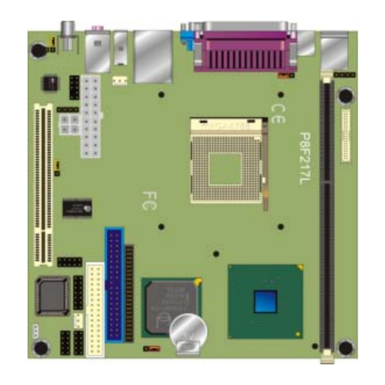
Page 10: Component Placement
S/P DIF, Line-in/out, Mic-in Agere FW323 IEEE1394 and CD-in Interface Controller Intel 845GV GMCH Intel 82801DB ICH4 With 400/533 MHz Host Bus With Hi-Speed USB 2.0 200 / 266 /333 MHz Memory UltraATA100 IDE Intel PRO/100+ LAN Mac P8F217 series User’s Manual... -
Page 11: Block Diagram
UltraATA100 IDE ATAPI Device Intel ICH4 100 MBps Hi-Speed USB 2.0 USB Devices 480 Mbps PCI Slot LAN1 PCI Bus Interface IEEE1394 Codec Audio Devices PS/2 Keyboard AT Keyboard PS/2 Mouse Floppy Serial Device Parallel Device P8F217 series User’s Manual... -
Page 12: Chapter 2. Hardware Setup
CPU and memory installation, fan, I/O and panel connections. 2. 1 Connector Location CPUFAN JKBV JAUDIO CDIN1 PCI1 IDE2 DIMM1 IDE1 FLOPPY JIR1 JRTC JFRNT CHASFAN JWOL COM1 USB1 Printer SVDIO1 RJACK1 VGA1 USRJ1 P1 RJACK2 P8F217 series User’s Manual... - Page 13 CPUFAN JAUDIO CDIN1 CONLCD PCI1 IDE2 DIMM1 IDE1 FLOPPY JIR1 JRTC JFRNT CHASFAN JWOL COM1 USB1 Printer SVDIO1 RJACK1 VGA1 USRJ1 P1 RJACK2 P8F217 series User’s Manual...
-
Page 14: Jumper Reference
S/P DIF Input / Output Setting Panel Voltage Setting Jumper Setting Quick Reference Jumper JRTC Clean CMOS Normal Operation JKBV KB with +5V KB with +5VSB IEEE1394 Enable IEEE1394 Disable S/P DIF Output S/P DIF Input +3.3V Default setting P8F217 series User’s Manual... -
Page 15: Connector Reference
AV TV-out RCA Jack Standard VGA1 VGA DB15 Female Connector Standard LAN RJ45 Connector with LED Standard USRJ1 Dual USB Connector Standard IEEE1394 Connector Standard Audio RCA Connector Standard RJACK2 S/P DIF Digital Audio Connector Standard P8F217 series User’s Manual... -
Page 16: Cpu And Dram Setting
The board’s data of CMOS can be setting in BIOS. If the board refuses to boot due to inappropriate CMOS settings, here is how to proceed to clear (reset) the CMOS to its default values. Jumper: JRTC Type: onboard 3-pin header JRTC Mode Clear CMOS Normal Operation Default setting JRTC P8F217 series User’s Manual... -
Page 17: Watchdog Timer Setting
2E, 07 2F, 08 Logical Device 8 2E, 30 Activate 2F, 01 2E, F5 Set as Second* 2F, 00 2E, F6 Set as 5 2F, 05 * Minute: bit 3 = 0; Second: bit 3 = 1 P8F217 series User’s Manual... -
Page 18: Embedded Solid State Disk
Embedded Solid State Disk The P8F217 series supports the IDE-based, bootable and driver free DiskOnModule (DOM) embedded flash disk. The onboard 40-pin IDE1 and 44-pin IDE2 box header supports normal DOM (DiskOnModule) or M- systems DiskOnChip IDE Pro flash disk with or without the additional Vcc power cable. -
Page 19: Power And Fan Connector
Ground Ground +12V +12V Connector: PW1 Type: 20-pin ATX power connector PIN assignment 3.3V 3.3V 3.3V -12V PS_ON PW_OK 5V_SB Connector: CPUFAN, SYSFAN Type: 3-pin fan wafer connector Pin Description Description Description Ground +12V Fan Control P8F217 series User’s Manual... -
Page 20: Vga Interface
Extreme Graphics with 266 MHz VGA core, 256-bit 3D engine and Intel Dynamic Video Memory up to 64MBytes shared with system memory. The CRT / analog VGA interface includes one external DB15 female connector on bracket on board. P8F217 series User’s Manual... -
Page 21: Digital Vga Interface (P8F217L Only)
The board’s digital video interface provides LVDS flat panel. The built-in 40-pin dual channel 24-bits LVDS interface offers the economical solution for LVDS-based LCD display. CONLCD Connector: J4 Connector: J3 Type: 5-pin LVDS Power Header Type: 3-pin Power select Header Description Description ENABKL VCC3 +12V P8F217 Series User’s Manual... - Page 22 Connector: CONLCD Type: onboard 40-pin connector for LVDS connector Signal Signal LCDVCC LCDVCC ATX0- BTX0- ATX0+ BTX0+ ATX1- BTX1- ATX1+ BTX1+ ATX2- BTX2- ATX2+ BTX2+ ATXC- BTX3- ATXC+ BTX3+ ATX3- BTXC- ATX3+ BTXC+ PANELCLK PANELCLK PANELDATA PANELDATA P8F217 Series User’s Manual...
-
Page 23: Ethernet Interface
Ethernet Interface The P8F217 series is integrated with Intel PRO/100+ Fast Ethernet interface at the type of 10Base-T/100Base-TX auto-switching Fast Ethernet with full duplex and IEEE 802.3U compliant. The P8F217 series LAN interface is controlled by the Intel 82801DB ICH4 and 82562ET PHY, and connect with the external RJ45 connector on rear I/O panel. -
Page 24: Audio Interface
Audio Interface The P8F217 series offers the AC97 3D audio with 5.1-channel and S/P DIF interface based on Intel ICH4 and Realtek ALC650 codec. JAUDIO CDIN 1 2 3 4 Red: Center / Mic-in Blue: Rear / Line-in Green: Front / Line-out... - Page 25 Line Out – Left Line Out – Right Ground Jumper: J2 Type: onboard 3-pin header Mode S/P DIF Output S/P DIF Input Default setting Connector: CDIN Type: 4-pin header Description CD – Left Ground Ground CD – Right P8F217 Series User’s Manual...
-
Page 26: Switch And Indicator
2.10 Switch and Indicator JFRNT Connector: JFRNT Type: onboard 14-pin (2 x 7) 2.54-pitch header Function Signal Signal Function Vcc (+) (+) Vcc IDE LED Power Active Reset Reset Speaker Power PWRBT Button SPKIN P8F217 Series User’s Manual... - Page 27 Notes (This page left blank intentionally) P8F217 Series User’s Manual...
-
Page 28: Chapter 3. Bios Setup
>Power Management Setup Set User Password >PnP / PCI Configurations Save & Exit Setup >PC Health Status Exit Without Saving ↑ ↓ → ← : Select Item Esc : Quit F10 : Save & Exit Setup P8F217 Series User’s Manual... - Page 29 Notes (This page left blank intentionally) P8F217 Series User’s Manual...
-
Page 30: Chapter 4 Audio Channel Configuration
Chapter 4 Audio Channel Configuration In order to enable 5.1 channel, please follow the setup steps below: lunch the Control Panel lunch the Sound Effect Manager 3.select Speaker Configuration and choose 6 channel mode for 5.1 speaker output P8F217 Series User’s Manual... - Page 31 Notes (This page left blank intentionally) P8F217 Series User’s Manual...
-
Page 32: Chapter 5. Display Settings
Please setup the display device properly before you boot up the system. For configure your Display device, please follow the instructions below: 1. lunch the display properties. 2. Select settings option and click Advanced Button 3. Select Intel(R) Extreme Graphics and click Graphics properties P8F217 Series User’s Manual... - Page 33 4. There will be a different device list depends on your connecting devices For Monitor: You can configure the Colors, Screen area (resolution) and Refresh Rate. For Notebook: If you connect a LCD panel though LVDS interface, you can configure the Colors and Screen Area (resolution) here. P8F217 Series User’s Manual...
- Page 34 If you connect the Monitor and LCD panel at the same time, here can let you configure if you want to have a clone dual display function. (Notice: TV-out does not have the ability with dual display.) P8F217 Series User’s Manual...
- Page 35 Notes (This page left blank intentionally) P8F217 Series User’s Manual...
-
Page 36: Appendix. A I/O Port Pin Assignment
Appendix. A I/O Port Pin Assignment IDE Port Connector: IDE1 Type: 40-pin (20 x 2) box header Description Description Reset Ground Ground Ground IOW-/STOP Ground IOR-/HDMARDY Ground IORDY/DDMARDY IDESEL DACK- Ground CBLID CS0 (MASTER CS) CS1 (SLAVE CS) LED ACT- Ground P8F217 Series User’s Manual... - Page 37 Connector: IDE2 Type: 44-pin (22 x 2) box header Description Description Reset Ground Ground Ground IOW-/STOP Ground IOR-/HDMARDY Ground IORDY/DDMARDY Ground DACK- Ground ASP1 Ground Ground Ground P8F217 Series User’s Manual...
-
Page 38: Floppy Port
Ground STEP- Ground WRITE DATA- Ground WRITE GATE- Ground TRACK 0- Ground WRITE PROTECT- Ground READ DATA- Ground HEAD SELECT- Ground DISK CHANGE- Serial Port Connector: JCOM1 Type: 10-pin (5 x 2) header Description Description Ground P8F217 Series User’s Manual... -
Page 39: Usb Port
Type: 10-pin (5 x 2) header for dual USB Ports Description Description Data0- Data1- Data0+ Data1+ Ground Ground IrDA Port Connector: JIR1 Type: 10-pin (5 x 2) header for SIR/CIR Ports Description Description CIRRX IRRX 5V Standby Ground IRTX P8F217 Series User’s Manual... -
Page 40: Vga Port
Connector: VGA Type: 15-pin D-sub female connector on bracket Description Description Description Ground GREEN Ground 5VCDA BLUE Ground HSYNC LVGA5V VSYNC Ground Ground 5VCLK LAN Port Connector: LAN Type: RJ45 connector with LED on bracket Description P8F217 Series User’s Manual... - Page 41 Notes (This page left blank intentionally) P8F217 Series User’s Manual...
-
Page 42: Appendix B. Flash The Bios
Get the “.bin” file including the image of new BIOS you want to update. Power on the system and flash the BIOS. Re-star the system. Any question about the BIOS re-flash please contact your distributors or visit our website at below: http://www.freetech.com P8F217 Series User’s Manual... - Page 43 Notes (This page left blank intentionally) P8F217 Series User’s Manual...
-
Page 44: Appendix C. System Resources
PC Compatible Eisa/Isa HAL 00C0-00CF PC Compatible Eisa/Isa HAL 00F0-00FF PC Compatible Eisa/Isa HAL 01CE-01CF VgaSavve 01F0-01F7 atapi 02F8-02FE Serial 0378-037A Parport 03B0-03BB VgaSavve 03C0-03DF VgaSavve 03F0-03F5 Floppy 03F6-03F6 atapi 03F7-03F7 Floppy 03F8-03FE Serial E000-E0FF alcxnt E400-E43F alcxnt P8F217 Series User’s Manual... -
Page 45: Memory Address Map
Intel (R) USB Enhanced Host Controller (ICH4) 0xEC000000-0xEC000FFF Intel(R) PRO/100 VE Network Connection 0xEC001000-0xEC001FFF OHCI Compliant IEEE 1394 Host Controller 0xFEBFFC00-0xFEBFFFFF Intel(R) 82801DB Ultra ATA Storage Controller - 24CB 0xEC181000-0xEC1811FF Avance AC'97 Audio 0xEC182000-0xEC1820FF Avance AC'97 Audio P8F217 Series User’s Manual... -
Page 46: System Irq And Dma Resource
Intel(R) 82801DB/DBM USB Universal Host Controller – 24C7 PS/2 Compatible Mouse Port Numeric Data Processor Intel(R) 82801DB Ultra ATA Storage Controller – 24CB Primary IDE Controller (Dual FIFO) Intel(R) 82801DB Ultra ATA Storage Controller – 24CB Secondary IDE Controller (Dual FIFO) P8F217 Series User’s Manual... - Page 47 C3.2 DMA Channel Device (free) (free) Standard Floppy Disk Controller (free) Direct Memory Access Controller (free) (free) (free) P8F217 Series User’s Manual...
-
Page 48: Online Services
Online Services Flexus Computer Technology, under the Freetech brand name, has consistently won recognition for excellence in the design and manufacturing of high quality mainboards! Our products are globally recognized among the leading cost- performance mainboards in the industry today and we are a...
Need help?
Do you have a question about the P8F217 Series and is the answer not in the manual?
Questions and answers