Table of Contents
Advertisement
Quick Links
Advertisement
Table of Contents

Related Manuals for Pilz PST 4


Summary of Contents for Pilz PST 4
- Page 1 PST 4 Operating Manual-18436-EN-09 - Safety relays...
- Page 2 We do assure you that all persons are regarded without discrim- ination and on an equal basis. All rights to this documentation are reserved by Pilz GmbH & Co. KG. Copies may be made for the user's internal purposes. Suggestions and comments for improving this documenta- tion will be gratefully received.
-
Page 3: Table Of Contents
Status indicators........................13 Faults – Interference ......................13 Dimensions in mm .........................14 Technical details ........................15 Safety characteristic data......................19 Supplementary data .......................20 Service life graph ........................20 Order reference ........................21 EC declaration of conformity ....................21 UKCA-Declaration of Conformity ..................21 Operating Manual PST 4 18436-EN-09... -
Page 4: Introduction
PST 4 Introduction Validity of documentation This documentation is valid for the product PST 4. It is valid until new documentation is published. This operating manual explains the function and operation, describes the installation and provides guidelines on how to connect the product. -
Page 5: Safety
This gives advice on applications and provides information on special fea- tures. Safety Intended use The safety relay PST 4 provides a safety-related interruption of a safety circuit. The safety relay meets the requirements of EN 60947-5-1 and EN 60204-1 and may be used in applications with: Safety gates... -
Page 6: Use Of Qualified Personnel
Note for overvoltage category III: If voltages higher than low voltage (>50 VAC or >120 VDC) are present on the unit, connected control elements and sensors must have a rated insulation voltage of at least 250 V. Operating Manual PST 4 18436-EN-09... -
Page 7: Unit Features
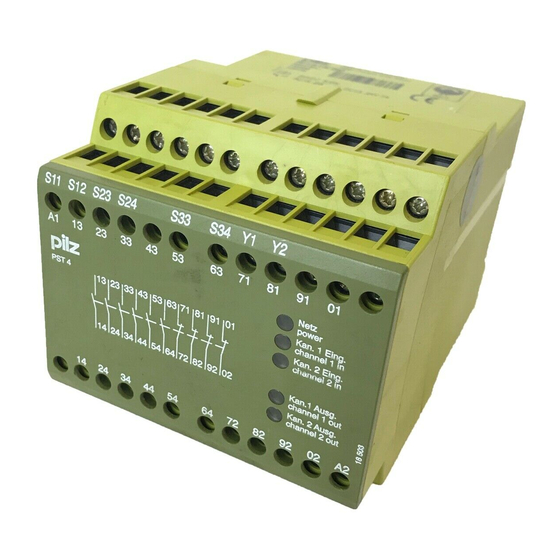
14 24 34 44 54 02 A2 14 24 34 44 54 64 S33 S34 *Insulation between the non-marked area and the relay contacts: Basic insulation (over- voltage category III), Protective separation (overvoltage category II) Operating Manual PST 4 18436-EN-09... -
Page 8: Function Description
71-72, 81-82, 91-92 and 01-02 are closed. – The LEDs "CH.1 OUT" and "CH.2 OUT" go out. If the input circuits have already switched before supply voltage is applied, the PST 4 stops the plant being enabled, to prevent an automatic start-up in accordance with EN 60204 Pt 7.5. -
Page 9: Timing Diagram
Use the notch on the rear of the unit to attach it to a DIN rail (35 mm). When installed vertically: Secure the unit by using a fixing element (e.g. retaining bracket or end angle). Operating Manual PST 4 18436-EN-09... -
Page 10: Wiring
Do not switch low currents using contacts that have been used previously with high cur- rents. On 24 VDC devices: The power supply must comply with the regulations for extra low voltages with protective electrical separation (SELV, PELV) in accordance with VDE 0100, Part 410. Operating Manual PST 4 | 10 18436-EN-09... -
Page 11: Preparing For Operation
In the event of an automatic start or manual start with bridged start contact (fault): The unit starts up automatically when the safeguard is reset, e.g. when the E-STOP pushbutton is released. Use external circuit measures to prevent an unexpected restart. Operating Manual PST 4 | 11 18436-EN-09... - Page 12 The feedback circuit must be closed at least 500 ms before limit switch S1 is operated and may only be opened once limit switch S1 has been oper- ated. Legend S1/S2: Safety gate switch S3: Start button : Switch operated : Gate open : Gate closed Operating Manual PST 4 | 12 18436-EN-09...
-
Page 13: Operation
LED "POWER" does not light: Short circuit or no supply voltage. CH.1 OUT and CH.2 OUT do not light: Only one limit switch is closed. Simultaneity was not maintained. Operating Manual PST 4 | 13 18436-EN-09... -
Page 14: Dimensions In Mm
PST 4 Dimensions in mm Operating Manual PST 4 | 14 18436-EN-09... -
Page 15: Technical Details
UB DC 100 Ohm Relay outputs Number of output contacts Safety contacts (N/O), instantaneous Auxiliary contacts (N/C) Max. short circuit current IK 1 kA Utilisation category in accordance with the standard EN 60947-4-1 Operating Manual PST 4 | 15 18436-EN-09... - Page 16 DC13 (6 cycles/min) at 24 V Max. current Utilisation category in accordance with UL Voltage 240 V AC G. P. with current Voltage 24 V DC Resistive with current Pilot Duty B300, R300 Operating Manual PST 4 | 16 18436-EN-09...
- Page 17 Supply interruption before de-energisation 10 ms Simultaneity, channel 1 and 2 max. Environmental data Climatic suitability EN 60068-2-78 Ambient temperature Temperature range -10 - 55 °C Storage temperature Temperature range -40 - 85 °C Operating Manual PST 4 | 17 18436-EN-09...
- Page 18 Torque setting with screw terminals 0,5 Nm Stripping length with screw terminals 6 mm Dimensions Height 87 mm Width 90 mm Depth 121 mm Weight 530 g Where standards are undated, the 2022-09 latest editions shall apply. Operating Manual PST 4 | 18 18436-EN-09...
-
Page 19: Safety Characteristic Data
A safety function's SIL/PL values are not identical to the SIL/PL values of the units that are used and may be different. We recommend that you use the PAScal software tool to calculate the safety function's SIL/PL values. Operating Manual PST 4 | 19 18436-EN-09... -
Page 20: Supplementary Data
To increase the service life, sufficient spark suppression must be provided on all output contacts. With capacitive loads, any power surges that occur must be noted. With DC con- tactors, use flywheel diodes for spark suppression. Operating Manual PST 4 | 20 18436-EN-09... -
Page 21: Order Reference
This product/these products meet the requirements of the directive 2006/42/EC for ma- chinery of the European Parliament and of the Council. The complete EC Declaration of Conformity is available on the Internet at www.pilz.com/downloads. Authorised representative: Norbert Fröhlich, Pilz GmbH & Co. KG, Felix-Wankel-Str. 2, 73760 Ostfildern, Germany UKCA-Declaration of Conformity This product(s) complies with following UK legislation: Supply of Machinery (Safety) Regu- lation 2008. - Page 22 We are represented internationally. Please refer to our homepage www.pilz.com for further details or contact our headquarters. Headquarters: Pilz GmbH & Co. KG, Felix-Wankel-Straße 2, 73760 Ostfildern, Germany Telephone: +49 711 3409-0, Telefax: +49 711 3409-133, E-Mail: info@pilz.com, Internet: www.pilz.com...
Need help?
Do you have a question about the PST 4 and is the answer not in the manual?
Questions and answers