Table of Contents
Advertisement
Available languages
Available languages
Quick Links
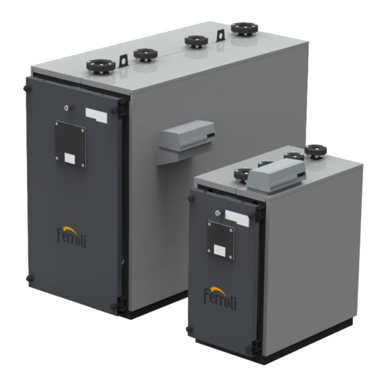
TP3 COND 65÷1000
Caldaia a condensazione ad Altissimo Rendimento pressurizzata in acciaio
Caldera por condensación de altísimo rendimiento presurizada de acero
Highly efficiency pressurized condensing boiler in steel
Chaudière à condensation à très haut rendement pressurisée en acier
IT
MANUALE PER L'INSTALLAZIONE, L'USO E LA MANUTENZIONE
ES
MANUAL DE INSTALACIÓN, USO Y MANTENIMIENTO
EN
INSTALLATION, USE AND MAINTENANCE MANUAL
FR
NOTICE POUR L'INSTALLATION, L'UTILISATION ET L'ENTRETIEN
Advertisement
Chapters
Table of Contents

Subscribe to Our Youtube Channel
Related Manuals for Ferroli TP3 COND 65-1000


Summary of Contents for Ferroli TP3 COND 65-1000
- Page 1 TP3 COND 65÷1000 Caldaia a condensazione ad Altissimo Rendimento pressurizzata in acciaio Caldera por condensación de altísimo rendimiento presurizada de acero Highly efficiency pressurized condensing boiler in steel Chaudière à condensation à très haut rendement pressurisée en acier MANUALE PER L’INSTALLAZIONE, L’USO E LA MANUTENZIONE MANUAL DE INSTALACIÓN, USO Y MANTENIMIENTO INSTALLATION, USE AND MAINTENANCE MANUAL NOTICE POUR L’INSTALLATION, L’UTILISATION ET L’ENTRETIEN...
-
Page 2: Table Of Contents
TP3 COND 1. Avvertenze generali ..................................3 2. Certificazioni ....................................3 3. Presentazione ....................................4 4. Caratteristiche tecniche, costruttive e dimensionali ....................... 4 Descrizione dellʼapparecchio ..................................4 Principio di funzionamento ..................................... 4 Dati tecnici - Dimensioni - Attacchi idraulici ..............................5 Identificazione ......................................13 5. Installazione .................................... -
Page 3: Avvertenze Generali
• Prima di effettuare qualsiasi operazione di pulizia o di manutenzione, disinserire l’apparecchio dalla rete di alimentazione. • La FERROLI non risponde per danni a persone e/a cose dovuti ad errori di installazione, di regolazione, di manutenzione e da usi im- propri. -
Page 4: Presentazione
TP3 COND PRESENTAZIONE Gentile Cliente, La ringraziamo per aver scelto una caldaia TP3 COND. Questo manuale è stato preparato per informarLa, con avvertenze e consigli, sulla installazione, il corretto uso e la manutenzione della caldaia. La preghiamo quindi di leggerlo attentamente e di conservarlo con cura per ogni ulteriore consultazione. Nel suo interesse, La invitiamo a seguire e osservare con attenzione quanto in esso contenuto per poter al meglio e con piena soddisfazione usufruire di questo prodotto di alta qualità. -
Page 5: Dati Tecnici - Dimensioni - Attacchi Idraulici
TP3 COND 4.3 Dati tecnici - Dimensioni - Attacchi idraulici fig. 2 - Dimensioni e attacchi Legenda Pannello strumenti Mandata riscaldamento Flangia attacco bruciatore Ritorno alta temperatura Portina di pulizia camera fumo Ritorno bassa temperatura Spia controllo fiamma Attacco vaso espansione Agganci per sollevamento Attacco scarico caldaia Fori per aggancio sollevamento Attacco camino Attacco scarico condensa cod. - Page 6 TP3 COND 4.3.1 Tabella dati tecnici, dimensioni e attacchi Nella colonna a destra viene indicata l’abbreviazione utilizzata nella targhetta dati tecnici. TP3 COND Categoria Gas I2H (IT - ES) Pmax Pmin Pmax Pmin Pmax Pmin Pmax Pmin Pmax Pmin Pmax Pmin Pmax Pmin Portata termica (kW) .
- Page 7 TP3 COND TP3 COND 1000 Categoria Gas Pmax Pmin Pmax Pmin Portata termica (kW) Qn (Hi) Potenza nominale utile (80/60°C) (kW) P 80° - 60° 1000 P 50° - 30° Potenza nominale utile (50/30°C) (kW) Gasolio 793.5 516.7 967.7 P 50° - 30° Rendimento (80/60°C) (%) 98.7 98.2...
- Page 8 TP3 COND Scheda prodotto ErP MODELLO: TP3 COND 65 (OIL) Marchio: FERROLI Caldaia a condensazione: SI Caldaia a bassa temperatura (**): NO Caldaia di tipo B1: NO Apparecchio di riscaldamento misto: NO Apparecchio di cogenerazione per il riscaldamento d’ambiente: NO Elemento Simbolo Unità...
- Page 9 TP3 COND Scheda prodotto ErP MODELLO: TP3 COND 100 (OIL) Marchio: FERROLI Caldaia a condensazione: SI Caldaia a bassa temperatura (**): NO Caldaia di tipo B1: NO Apparecchio di riscaldamento misto: NO Apparecchio di cogenerazione per il riscaldamento d’ambiente: NO Elemento Simbolo Unità...
- Page 10 TP3 COND Scheda prodotto ErP MODELLO: TP3 COND 150 (OIL) Marchio: FERROLI Caldaia a condensazione: SI Caldaia a bassa temperatura (**): NO Caldaia di tipo B1: NO Apparecchio di riscaldamento misto: NO Apparecchio di cogenerazione per il riscaldamento d’ambiente: NO Elemento Simbolo Unità...
- Page 11 TP3 COND Scheda prodotto ErP MODELLO: TP3 COND 230 (OIL) Marchio: FERROLI Caldaia a condensazione: SI Caldaia a bassa temperatura (**): NO Caldaia di tipo B1: NO Apparecchio di riscaldamento misto: NO Apparecchio di cogenerazione per il riscaldamento d’ambiente: NO Elemento Simbolo Unità...
- Page 12 TP3 COND Scheda prodotto ErP MODELLO: TP3 COND 370 (OIL) Marchio: FERROLI Caldaia a condensazione: SI Caldaia a bassa temperatura (**): NO Caldaia di tipo B1: NO Apparecchio di riscaldamento misto: NO Apparecchio di cogenerazione per il riscaldamento d’ambiente: NO Elemento Simbolo Unità...
-
Page 13: Identificazione
Viene applicata, nella parte alta anteriore di uno dei pannelli laterali della mantellatura, in modo visibile. In caso di smarrimento richiederne un duplicato al Servizio Tecnico di Assistenza FERROLI. La manomissione, l’asportazione, la mancanza della targhetta di identificazione o quant’altro non permetta la sicura identificazione del prodotto, rende difficoltosa qualsiasi operazione di installazione e manutenzione. -
Page 14: Locale Di Installazione
TP3 COND 5.3 Locale di installazione Le caldaie TP3 COND vanno installate in locali ad uso esclusivo, rispondenti alle Norme Tecniche e alla Legislazione vigente e dotati di aperture di aerazione adeguatamente dimensionate. Le aperture di aerazione dovranno essere permanenti, comunicanti direttamente con l’esterno e posizionate a livello alto e basso in conformità... -
Page 15: Scarico Dei Prodotti Della Combustione
TP3 COND 5.4 Scarico dei prodotti della combustione anale da fumo e il raccordo alla canna fumaria devono essere realizza- Il c ti in conformità alle Norme e alla Legislazione vigente, con condotti rigidi, resistenti alla temperatura, alla condensa, alle sollecitazioni meccaniche e a tenuta. La canna fumaria deve assicurare la depressione minima prevista dalle Norme vigenti, considerando pressione “zero”... - Page 16 TP3 COND 5.5.2 Tubazioni mandata/ritorno impianto Le dimensioni delle tubazioni di mandata e ritorno sono indicate per ogni modello di caldaia nella tabella DIMENSIONI. Assicurarsi che sull’impianto ci sia un numero sufficiente di sfiati. Gli attacchi della caldaia non devono essere sollecitati dal peso delle tubazioni d’allacciamento all’impianto.
-
Page 17: Porta Anteriore Apertura E Regolazione
TP3 COND 5.6 Porta anteriore apertura e regolazione Prendere nota della misura “X” di fig. 9 sui 4 angoli della porta. Svitare i 4 dadi “A” e controdadi “B” portandoli verso l’esterno fino a fine filetto. Fare attenzione a non far cadere la porta dalle svasature dei 4 dadi “A”. -
Page 18: Montaggio Del Bruciatore
TP3 COND 5.7 Montaggio del bruciatore Il montaggio del bruciatore alla porta della caldaia, deve garantire una perfetta tenuta ai prodotti della combustione. Installato il bruciatore sulla caldaia, lo spazio tra il boccaglio del bruciatore e il materiale refrattario del portellone deve essere riempito con il materassino cera- mico (rif. -
Page 19: Posizionamento Della Sonda E Dei Bulbi
TP3 COND 5.9 Posizionamento della sonda e dei bulbi Il pannello di controllo è dotato di una sonda di temperatura e tre bulbi. Sono presenti due pozzetti “A” e “B” vicino alla mandata riscaldamento “T1” (vedi fig. 15). È OBBLIGATORIO inserire nel pozzetto “A” (fig. 17) la sonda di temperatura “4” e il bulbo del termostato di sicurezza “3”. Inserire nel pozzetto “B”... -
Page 20: Schema Di Principio - Impianto Per Riscaldamento E Produzione Di Acqua Sanitaria
TP3 COND SCHEMA DI PRINCIPIO - IMPIANTO PER RISCALDAMENTO E PRODUZIONE DI ACQUA SANITARIA La scelta e l’installazione dei componenti dell’impianto è demandata per competenza all’installatore, che dovrà operare secondo le regole della buona tecnica e della Legislazione vigente. Gli impianti caricati con antigelo obbligano l’impiego di disconnettori idrici. Si ricorda che lo schema di fig. -
Page 21: Avviamento
TP3 COND AVVIAMENTO 7.1 Controlli preliminari Eseguiti i collegamenti idraulici, elettrici e del combustibile alla caldaia, prima dell’avviamento controllare che: • Il vaso di espansione e la valvola di sicurezza (se necessaria) siano collegati in maniera corretta e non siano in alcun modo intercettabili. •... -
Page 22: Pulizia Della Caldaia
TP3 COND 8.4 Pulizia della caldaia Per effettuare la pulizia procedere nel seguente modo (vedi fig. 20 e fig. 21): • Aprire il portello anteriore (rif. 1) ed estrarre i turbolatori (rif. 2). • Pulire le superfici interne della camera di combustione e del percorso fumi utilizzando uno scovolo (3 - Non fornito) o altri utensili adeguati allo scopo. -
Page 23: Verifica Di Funzionamento Del Bruciatore
TP3 COND 8.6 Verifica di funzionamento del bruciatore - Consultare il manuale d’istruzioni del bruciatore. - Seguire tutte le prescrizioni di norme locali in materia di manutenzione al bruciatore. 8.7 Possibili guasti e rimedi Di seguito una lista con le indicazioni dei principali guasti o anomalie che si possono verificare nella gestione della caldaia, con specificate le possibili cause e i relativi rimedi. - Page 24 ��������� Nel solo caso in cui alla caldaia venga abbinato un bruciatore a marchio Ferroli, entro 30 giorni dalla messa in servizio il Cliente deve richiedere ad un garanzia convenzionale che in questo caso avrà validità 24 mesi. Trascorsi oltre 30 giorni dalla messa in servizio la Garanzia Convenzionale non sarà...
- Page 25 TP3 COND 1. Advertencias generales ................................26 2. Certificaciones ..................................26 3. Presentación ....................................27 4. Características técnicas, constructivas y dimensionales ..................... 27 Descripción del aparato ....................................27 Principio de funcionamiento ..................................27 Datos técnicos - Medidas - Conexiones hidráulicas ............................ 28 Identificación ........................................ 36 5.
-
Page 26: Advertencias Generales
• Antes de realizar cualquier operación de limpieza o mantenimiento hay que desconectar el aparato de la red de alimentación. • FERROLI no responde de daños personales o materiales debidos a errores de instalación, regulación, mantenimiento o usos inadecua- dos. -
Page 27: Presentación
TP3 COND PRESENTACIÓN Estimado Cliente: Gracias por elegir una caldera TP3 COND. Este manual ha sido redactado para informarle sobre la instalación, el uso correcto y el mante- nimiento de la caldera, e incluye advertencias y consejos. Le rogamos leerlo atentamente y conservarlo con cuidado para cualquier consulta futura. Por su interés, le invitamos a seguir y observar con atención todas las instrucciones para aprovechar al máximo este producto de alta calidad. -
Page 28: Datos Técnicos - Medidas - Conexiones Hidráulicas
TP3 COND 4.3 Datos técnicos - Medidas - Conexiones hidráulicas fig. 2 - Medidas y conexiones Leyenda Panel de instrumentos Ida calefacción Brida conexión quemador Retorno alta temperatura Puerta limpieza cámara de humo Retorno baja temperatura Piloto de control de llama Conexión depósito de expansión Ganchos de elevación Conexión descarga caldera Orificios para los ganchos de elevació... - Page 29 TP3 COND 4.3.1 Tabla de datos técnicos, medidas y conexiones En la columna derecha se indica la abreviatura utilizada en la placa de datos técnicos. TP3 COND Categoría Gas I2H (IT - ES) Pmax Pmin Pmax Pmin Pmax Pmin Pmax Pmin Pmax Pmin Pmax Pmin Pmax Pmin Capacidad térmica (kW) .
- Page 30 TP3 COND TP3 COND 1000 Categoría Gas Pmax Pmin Pmax Pmin Capacidad térmica (kW) Qn (Hi) Potencia nominal útil (80/60°C) (kW) P 80° - 60° 1000 P 50° - 30° Potencia nominal útil (50/30°C) (kW) Gasóleo 793.5 516.7 967.7 P 50° - 30° Rendimiento (80/60°C) (%) 98.7 98.2...
- Page 31 TP3 COND Ficha del producto ErP MODELO: TP3 COND 65 (OIL) Marca comercial: FERROLI Caldera de condensación: SI Caldera de baja temperatura (**): NO Caldera B1: NO Calefactor combinado: NO Aparato de calefacción de cogeneración: NO Elemento Simbolo Unidad Valor Clase de eficiencia energética estacional de calefacción Potencia calorífica nominal...
- Page 32 TP3 COND Ficha del producto ErP MODELO: TP3 COND 100 (OIL) Marca comercial: FERROLI Caldera de condensación: SI Caldera de baja temperatura (**): NO Caldera B1: NO Calefactor combinado: NO Aparato de calefacción de cogeneración: NO Elemento Simbolo Unidad Valor Potencia calorífica nominal ƞ Eficiencia energética estacional de calefacción Potencia calorífica útil...
- Page 33 TP3 COND Ficha del producto ErP MODELO: TP3 COND 150 (OIL) Marca comercial: FERROLI Caldera de condensación: SI Caldera de baja temperatura (**): NO Caldera B1: NO Calefactor combinado: NO Aparato de calefacción de cogeneración: NO Elemento Simbolo Unidad Valor Potencia calorífica nominal ƞ Eficiencia energética estacional de calefacción Potencia calorífica útil...
- Page 34 TP3 COND Ficha del producto ErP MODELO: TP3 COND 230 (OIL) Marca comercial: FERROLI Caldera de condensación: SI Caldera de baja temperatura (**): NO Caldera B1: NO Calefactor combinado: NO Aparato de calefacción de cogeneración: NO Elemento Simbolo Unidad Valor Potencia calorífica nominal ƞ Eficiencia energética estacional de calefacción Potencia calorífica útil...
- Page 35 TP3 COND Ficha del producto ErP MODELO: TP3 COND 370 (OIL) Marca comercial: FERROLI Caldera de condensación: SI Caldera de baja temperatura (**): NO Caldera B1: NO Calefactor combinado: NO Aparato de calefacción de cogeneración: NO Elemento Simbolo Unidad Valor Potencia calorífica nominal ƞ Eficiencia energética estacional de calefacción Potencia calorífica útil...
-
Page 36: Identificación
Está aplicada en la parte superior delantera de uno de los paneles laterales del revestimiento, de manera visible. En caso de pérdida de la placa, pedir un duplicado al servicio de asistencia técnica. FERROLI. La alteración, eliminación o ausencia de la placa de identificación o cualquier acción que impida la identificación del producto dificultará las operaciones de instalación y mantenimiento. -
Page 37: Local De Instalación
TP3 COND 5.3 Local de instalación Las calderas TP3 COND se deben instalar en locales para uso exclusivo, conformes a las normas técnicas y a la legislación vigente, dotados de aberturas de aireación del tamaño adecuado. Las aberturas deben ser permanentes y estar comunicadas directamente con el exterior, a una altura conforme a las normas vigentes. -
Page 38: Descarga De Los Productos De Combustión
TP3 COND 5.4 Descarga de los productos de combustión anal de humo y la conexión al humero deben estar realizadas de El c conformidad con las normas y la legislación vigentes, con conductos rígidos, resistentes a las altas temperaturas, a la condensación y a los esfuerzos mecánicos, y estancos. - Page 39 TP3 COND 5.5.2 Tubos de ida/retorno de la instalación Las medidas de los tubos de ida y retorno se indican por modelo de caldera en la tabla de MEDIDAS. Asegurarse de que en la instalación haya suficientes válvulas de salida. Las conexiones de la caldera no deben ser sometidas a esfuerzo por el peso de los tubos de conexión a la instalación.
-
Page 40: Puerta Delantera, Apertura Y Regulación
TP3 COND 5.6 Puerta delantera, apertura y regulación Tomar nota de la medida “X” de fig. 9 en los 4 ángulos de la puerta. Desenroscar las 4 tuercas “A” y contratuercas “B” sacándolas hasta el fin de la rosca. Prestar atención para no dejar caer la puerta del abocardado de las 4 tuercas “A”. -
Page 41: Montaje Del Quemador
TP3 COND 5.7 Montaje del quemador El montaje del quemador en la puerta de la caldera debe garantizar una perfecta estanqueidad a los productos de combustión. Instalado el quemador en la caldera, el espacio entre la boca del quemador y el material refractario de la puerta se debe llenar con el colchón cerámico (ref. -
Page 42: Colocación De La Sonda Y Los Bulbos
TP3 COND 5.9 Colocación de la sonda y los bulbos El panel de control está dotado de una sonda de temperatura y tres bulbos. Hay dos alojamientos, “A” y “B”, cerca de la ida de la calefacción “T1” (ver fig. 15). ES OBLIGATORIO poner en el alojamiento “A” (fig. 17) la sonda de temperatura “4” y el bulbo del termostato de seguridad “3”. Poner en el alojamiento “B”... -
Page 43: Esquema Preliminar - Instalación Para Calefacción Y Producción De Agua Sanitaria
TP3 COND ESQUEMA PRELIMINAR - INSTALACIÓN PARA CALEFACCIÓN Y PRODUCCIÓN DE AGUA SANITARIA La selección e instalación de los componentes corresponde al instalador, que debe operar según las reglas de la buena técnica y la legi- slación vigente. Las instalaciones cargadas con anticongelante exigen el empleo de desconectores hídricos. Se recuerda que el esquema de fig. -
Page 44: Puesta En Marcha
TP3 COND PUESTA EN MARCHA 7.1 Controles preliminares Realizadas las conexiones hidráulicas, eléctricas y del combustible a la caldera, antes de la puesta en marcha comprobar que: • El depósito de expansión y la válvula de seguridad (si es necesaria) estén conectados correctamente y no se puedan interceptar. •... -
Page 45: Limpieza De La Caldera
TP3 COND 8.4 Limpieza de la caldera Para la limpieza hay que proceder de la siguiente manera (ver fig. 20 y fig. 21): • Abrir la puerta delantera (ref. 1) y extraer los turboladores (ref. 2). • Limpiar las superficies internas de la cámara de combustión y del recorrido de los humos utilizando un escobillón (3 - no suministrado) u otras herramientas adecuadas. -
Page 46: Verificación Del Funcionamiento Del Quemador
TP3 COND 8.6 Verificación del funcionamiento del quemador - Consultar el manual de instrucciones del quemador. - Seguir todas las prescripciones de las normas locales en materia de mantenimiento del quemador. 8.7 Problemas y soluciones posibles A continuación se enumeran los principales problemas o anomalías que pueden ocurrir durante la gestión de la caldera, las causas posibles y las respectivas soluciones. - Page 47 • instrucciones técnicas suministradas con los equipos. Sera necesario presentar al personal técnico de FERROLI, antes de su intervención, la factura o ticket de • compra del aparato, junto al albarán de entrega correspondiente, si este fuese de fecha posterior.
- Page 48 TP3 COND 1. General instructions ................................. 49 2. Certifications ..................................... 49 3. Introduction ....................................50 4. Technical, constructive and dimensional characteristics ..................... 50 Description of unit ......................................50 Working principle ......................................50 Technical data - Dimensions - Hydraulic connections ..........................51 Identification .........................................
-
Page 49: General Instructions
• Installation must be carried out by suitably qualified personnel, in accordance with current regulations. • Disconnect the unit from the power supply before carrying out any cleaning or maintenance. • FERROLI declines any liability for damage to persons and/or property due to incorrect installation, adjustment and maintenance, and improper use. -
Page 50: Introduction
TP3 COND INTRODUCTION Dear Customer, Thank you for choosing a TP3 COND boiler. This manual has been prepared in order to provide instructions and advice on the installation, proper use and maintenance of the boiler. Please read it carefully and keep it for further consultation. Carefully follow the instructions provided, to ensure the best use of this high quality product. -
Page 51: Technical Data - Dimensions - Hydraulic Connections
TP3 COND 4.3 Technical data - Dimensions - Hydraulic connections fig. 2 - Dimensions and connections Legend Instrument panel Heating delivery Burner connection flange High temperature return Smoke chamber cleaning door Low temperature return Flame control sight glass Expansion vessel connection Lifting hooks Boiler discharge connection Holes for lifting hook... - Page 52 TP3 COND 4.3.1 Table of technical data, dimensions and connections The column on the right gives the abbreviation used on the data plate. TP3 COND Gas category I2H (IT - ES) Pmax Pmin Pmax Pmin Pmax Pmin Pmax Pmin Pmax Pmin Pmax Pmin Pmax Pmin Heat input (kW) .
- Page 53 TP3 COND TP3 COND 1000 Gas category Pmax Pmin Pmax Pmin Heat input (kW) Qn (Hi) Effective rated output (80/60°C) (kW) P 80° - 60° 1000 P 50° - 30° Effective rated output (50/30°C) (kW) 793.5 516.7 967.7 P 50° - 30° Efficiency (80/60°C) (%) 98.7 98.2...
- Page 54 TP3 COND ErP product fiche MODEL: TP3 COND 65 (OIL) Trademark: FERROLI Condensing boiler: YES Low-temperature boiler (**): NO B1 Boiler: NO Combination heater: NO Cogeneration space heater: NO Item Symbol Unit Value Seasonal space heating energy efficiency class Rated heat output ƞ...
- Page 55 TP3 COND ErP product fiche MODEL: TP3 COND 100 (OIL) Trademark: FERROLI Condensing boiler: YES Low-temperature boiler (**): NO B1 Boiler: NO Combination heater: NO Cogeneration space heater: NO Item Symbol Unit Value Rated heat output ƞ Seasonal space heating energy efficiency...
- Page 56 TP3 COND ErP product fiche MODEL: TP3 COND 150 (OIL) Trademark: FERROLI Condensing boiler: YES Low-temperature boiler (**): NO B1 Boiler: NO Combination heater: NO Cogeneration space heater: NO Item Symbol Unit Value Rated heat output ƞ Seasonal space heating energy efficiency...
- Page 57 TP3 COND ErP product fiche MODEL: TP3 COND 230 (OIL) Trademark: FERROLI Condensing boiler: YES Low-temperature boiler (**): NO B1 Boiler: NO Combination heater: NO Cogeneration space heater: NO Item Symbol Unit Value Rated heat output ƞ Seasonal space heating energy efficiency...
- Page 58 TP3 COND ErP product fiche MODEL: TP3 COND 370 (OIL) Trademark: FERROLI Condensing boiler: YES Low-temperature boiler (**): NO B1 Boiler: NO Combination heater: NO Cogeneration space heater: NO Item Symbol Unit Value Rated heat output ƞ Seasonal space heating energy efficiency...
-
Page 59: Identification
It is applied in a visible place at the top of one of the casing side panels. If lost, ask the FERROLI After-Sales Service for a duplicate. Tampering, removal or lack of the identification plate prevents sure identification of the product, and makes any installation and maintenance operation difficult. -
Page 60: Installation Room
TP3 COND 5.3 Installation room TP3 COND boilers must be installed in dedicated rooms, meeting the current Technical Standards and Legislation and equipped with ade- quate ventilation openings. The ventilation openings must be permanent, communicating directly with the outside and located at the top and bottom in accordance with current regulations. -
Page 61: Discharge Of Combustion Products
TP3 COND 5.4 Discharge of combustion products lue pipe and flue connection must comply with the current Regulations The f and Legislation, using pipes that are resistant to heat, condensate and mechanical stresses, and be tight. The flue must ensure the minimum negative pressure required by the current Regulations, considering "zero"... - Page 62 TP3 COND 5.5.2 System delivery/return pipes The sizes of the delivery and return pipes are given for each boiler model in the DIMENSIONS table. Make sure the system has a sufficient number of vents. Boiler connections must not be stressed by the weight of the system connection pipes.
-
Page 63: Front Door Opening And Adjustment
TP3 COND 5.6 Front door opening and adjustment Take note of the measurement “X” in fig. 9 at the 4 corners of the door. Unscrew the 4 nuts “A” and locknuts “B” to near the end of the thread. Make sure the door does not fall off the flaring of the 4 nuts “A”. Nut “A”... -
Page 64: Burner Assembly
TP3 COND 5.7 Burner assembly Burner mounting on the boiler door must ensure perfect tightness to the combustion products. When the burner is installed on the boiler, the space between the burner nozzle and the refractory material of the door must be filled with the ceramic mat (ref. A - fig. 13) supplied. This prevents overheating of the door which would otherwise become permanently deformed. -
Page 65: Probe And Bulb Positioning
TP3 COND 5.9 Probe and bulb positioning The control panel is equipped with a temperature probe and three bulbs. There are two wells “A” and “B” near the heating delivery “T1” (see fig. 15). IT IS MANDATORY to insert in the well “A” (fig. 17) the temperature probe “4” and the safety thermostat bulb “3”. Insert in the well “B”... -
Page 66: Schematic Diagram - System For Heating And Domestic Hot Water
TP3 COND SCHEMATIC DIAGRAM - SYSTEM FOR HEATING AND DOMESTIC HOT WATER The choice and installation of the system components is up to the installer, who must operate according to good practice and the current Legislation. Systems with antifreeze require the use of backflow preventers. Remember that the diagram in fig. 19 is a schematic diagram. In case of different systems, please contact our After-Sales Service which will provide all the elements you require. -
Page 67: Startup
TP3 COND STARTUP 7.1 Preliminary checks After carrying out the plumbing, electrical and fuel connections to the boiler, before startup make sure: • The expansion vessel and the safety valve (if required) are properly connected and cannot be shut off in any way. •... -
Page 68: Boiler Cleaning
TP3 COND 8.4 Boiler cleaning To carry out cleaning, proceed as follows (see fig. 20 and fig. 21): • Open the front door (ref. 1) and remove the turbulators (ref. 2). • Clean the inside of the combustion chamber and flueways using a brush (3 - not supplied) or other implements suitable for the purpose. •... -
Page 69: Burner Operation Check
TP3 COND 8.6 Burner operation check - See the burner instruction manual. - Follow all the requirements of local regulations regarding burner maintenance. 8.7 Troubleshooting The following boiler troubleshooting guide gives the main faults or failures that may occur, with possible causes and cures. FAULT THE GENERATOR GETS DIRTY EASILY CAUSE:... - Page 70 TP3 COND 1. Précautions générales ................................71 2. Certifications ..................................... 71 3. Introduction ....................................72 4. Caractéristiques techniques, de construction et dimensionnelles ..................72 Descriptif de l'appareil ....................................72 Principe de fonctionnement ..................................72 Caractéristiques techniques - Dimensions - Raccords hydrauliques ......................73 Identification .........................................
-
Page 71: Précautions Générales
• Avant d'effectuer toute opération de nettoyage ou d'entretien, débrancher l'appareil de ses réseaux d'alimentation. • La société FERROLI ne répond pas des dommages aux personnes et/aux biens ou choses causés par des erreurs dans l'installation, le réglage et l'entretien et/ou résultant d'usages impropres et/ou inhabituels de l'appareil. -
Page 72: Introduction
TP3 COND INTRODUCTION Cher Client, Nous vous remercions d'avoir choisi une chaudière TP3 COND. Cette notice réunit à votre intention toutes les informations (précautions, consignes, conseils, etc.) qui vous permettront d'installer, d'utiliser et d'entretenir correctement votre chaudière. Nous vous prions de lire attentivement cette notice et de la conserver avec soin pour toute consultation future. Nous vous invitons, dans vo- tre intérêt, à... -
Page 73: Caractéristiques Techniques - Dimensions - Raccords Hydrauliques
TP3 COND 4.3 Caractéristiques techniques - Dimensions - Raccords hydrauliques fig. 2 - Dimensions et raccords Légende Panneau d'instruments Départ chauffage Bride de fixation du brûleur Retour haute température Trappe de nettoyage de la boîte à fumée Retour basse température Voyant de contrôle de la flamme Raccord vase d'expansion Oeillets de levage... - Page 74 TP3 COND 4.3.1 Tableau caractéristiques techniques, dimensions et raccords La colonne de droite indique l'abréviation utilisée sur la plaquette des caractéristiques techniques. TP3 COND Catégorie gaz I2H (IT - ES) Pmax Pmin Pmax Pmin Pmax Pmin Pmax Pmin Pmax Pmin Pmax Pmin Pmax Pmin Puissance thermique (kW) .
- Page 75 TP3 COND TP3 COND 1000 Catégorie gaz Pmax Pmin Pmax Pmin Puissance thermique (kW) Qn (Hi) Puissance nominale utile (80/60 °C) (kW) P 80° - 60° 1000 P 50° - 30° Puissance nominale utile (50/30 °C) (kW Gasoil 793.5 516.7 967.7 P 50°...
- Page 76 TP3 COND Fiche de produit ErP MODÈLE: TP3 COND 65 (OIL) Marque commerciale: FERROLI Chaudière à condensation: OUI Chaudière basse température (**): NO Chaudière de type B1: NO Dispositif de chauffage mixte: NO Dispositif de chauffage des locaux par cogénération: NO Caractéristique Symbole Unité...
- Page 77 TP3 COND Fiche de produit ErP MODÈLE: TP3 COND 100 (OIL) Marque commerciale: FERROLI Chaudière à condensation: OUI Chaudière basse température (**): NO Chaudière de type B1: NO Dispositif de chauffage mixte: NO Dispositif de chauffage des locaux par cogénération: NO Caractéristique Symbole Unité Valeur Puissance thermique nominale ƞ...
- Page 78 TP3 COND Fiche de produit ErP MODÈLE: TP3 COND 150 (OIL) Marque commerciale: FERROLI Chaudière à condensation: OUI Chaudière basse température (**): NO Chaudière de type B1: NO Dispositif de chauffage mixte: NO Dispositif de chauffage des locaux par cogénération: NO Caractéristique Symbole Unité Valeur Puissance thermique nominale ƞ...
- Page 79 TP3 COND Fiche de produit ErP MODÈLE: TP3 COND 230 (OIL) Marque commerciale: FERROLI Chaudière à condensation: OUI Chaudière basse température (**): NO Chaudière de type B1: NO Dispositif de chauffage mixte: NO Dispositif de chauffage des locaux par cogénération: NO Caractéristique Symbole Unité Valeur Puissance thermique nominale ƞ...
- Page 80 TP3 COND Fiche de produit ErP MODÈLE: TP3 COND 370 (OIL) Marque commerciale: FERROLI Chaudière à condensation: OUI Chaudière basse température (**): NO Chaudière de type B1: NO Dispositif de chauffage mixte: NO Dispositif de chauffage des locaux par cogénération: NO Caractéristique Symbole Unité Valeur Puissance thermique nominale ƞ...
-
Page 81: Identification
Cette plaque est appossé en haut à droite d'un des panneaux latéraux de l'habillage, de manière visible. En cas de perte, en demander un exemplaire à notre équipe du SAV FERROLI. La modification, la dépose, l'absence de la plaque d'identification ou quoi que ce soit d'autre permettant d'identifier sûrement l'appareil, rendront difficile l'exécution de toute opération d'installation et d'entretien. -
Page 82: Local D'installation
TP3 COND 4.7 Local d'installation Les chaudières TP3 COND doivent être installées dans des locaux à usage spécifique, répondant aux normes techniques et à la législation en vigueur et pourvus d'ouvertures d'aération adéquatement dimensionnées. Les ouvertures d'aération devront être permanentes, directe- ment communicantes avec l'extérieur et positionnées aux niveaux haut et bas en conformité... -
Page 83: Évacuation Des Produits De Combustion
TP3 COND 4.8 Évacuation des produits de combustion arneau et son raccordement doivent être réalisés conformément aux Le c normes et à la législation en vigueur, en utilisant des conduits rigides, résistants à la température, à la condensation, aux sollicitations mécani- ques et étanches. - Page 84 TP3 COND En cas de traitements physico-chimiques de l'eau appropriés, aussi bien de circuit que d'alimentation, ainsi que les contrôles correspon- dants à cyclicité élevée permettant de garantir les paramètres requis, pour des applications exclusivement industrielles, il est admis d'instal- ler le produit dans des installations à...
-
Page 85: Ouverture Et Réglage De La Porte Avant
TP3 COND 4.10 Ouverture et réglage de la porte avant Mesurer la cote « X » indiquée en fig. 9 sur les 4 angles de la porte. Dévisser les 4 écrous « A » et contre-écrous « B » en les amenant vers l'extérieur jusqu'à la fin du filet. Veiller à ne pas faire tomber la porte des décolletages des 4 écrous « A ». -
Page 86: Montage Du Brûleur
TP3 COND 4.11 Montage du brûleur Le montage du brûleur sur la porte de la chaudière doit garantir une parfaite étanchéité aux produits de combustion. Après le montage du brûleur sur la chaudière, l'espace entre l'embout du brûleur et la matériau réfractaire de la porte doit être rempli avec le matelas céramique (rep. -
Page 87: Positionnement De La Sonde Et Des Bulbes
TP3 COND 4.13 Positionnement de la sonde et des bulbes Le tableau de commande est doté d'une sonde de température et de trois bulbes. Deux fourreaux « A » et « B » sont montés près du départ chauffage « T1 » (voir fig. 15). IL EST OBLIGATOIRE de placer à l'intérieur du fourreau « A » (fig. 17) la sonde de température « 4 » et le bulbe du thermostat de sécurité « 3 ». -
Page 88: Schéma De Principe - Installation De Chauffage Et De Production D'ecs
TP3 COND SCHÉMA DE PRINCIPE - INSTALLATION DE CHAUFFAGE ET DE PRODUCTION D’ECS Le choix et l’installation des composants de l’installation est confiée exclusivement à l’installateur, lequel devra opérer conformément aux textes réglementaires et règles de l’art en vigueur. Les installations chargées d’antigel nécessitent la mise en place de disconnecteurs hydrauliques. -
Page 89: Allumage
TP3 COND ALLUMAGE 6.1 Contrôles préliminaires Effectuer les raccordements hydrauliques, électriques et du combustible à la chaudière ; avant la mise en route, contrôler les points suivants : • Le vase d’expansion et la soupape de sûreté (si nécessaire) doivent être correctement connectés et ne doivent pouvoir être en aucun cas interceptés. -
Page 90: Entretien Extraordinaire
TP3 COND 7.3 Entretien extraordinaire Entretien extraordinaire de fin de saison ou pour de longues périodes d’inutilisation. En plus d’effectuer les opérations décrites dans le chapitre précédent, il faudra : • Contrôler l’état d’usure des turbulateurs. • Ne pas vider l’installation et la chaudière. Les opérations effectuées devront être ensuite consignées sur le livret de la centrale. -
Page 91: Contrôle Du Fonctionnement Du Brûleur
TP3 COND • En agissant sur l’interrupteur principal du tableau de commande. • En agissant sur le thermostat d’ambiance ou sur le programmateur horaire ou sur la thermorégulation. • En vérifiant la rotation libre et correcte des circulateurs. • En vérifiant l’arrêt total de la chaudière en agissant sur l’interrupteur général de l’installation. Si toutes les conditions sont remplies, redémarrer l’appareil, effectuer un contrôle de la combustion (analyse des fumées), du débit du combustible et de l’étanchéité... - Page 92 FERROLI S.p.A. Via Ritonda 78/a 37047 San Bonifacio - Verona - ITALY www.ferroli.com Fabbricato in Italia - Fabricado en Italia Made in Italy - Fabriqué en Italie...
Need help?
Do you have a question about the TP3 COND 65-1000 and is the answer not in the manual?
Questions and answers