
Related Manuals for Light O Rama Aurora Core


Summary of Contents for Light O Rama Aurora Core
- Page 1 Aurora Core E1.31/Artnet 16 Port Smart Pixel Controller 2 DMX Ports and 2 Long Range Receiver Outputs User Manual November 2023 V1.0 Copyright © Light O Rama, Inc. 2023...
-
Page 2: Table Of Contents
Table of Contents Introduction Hardware Overview Getting Started - Connecting to a Network The term “DHCP” and why it is relevant for the Aurora Core How to Connect Isolated Network Part of your Existing DHCP Network Configuring Over Wifi Controller Setup - Web Interface... -
Page 3: Introduction
5VDC or 12VDC pixels (requires the corresponding power supply to be used). The Aurora Core has 2 DMX output ports, each allowing 1 universe of DMX data to be sent to any serial DMX capable device. This includes LOR AC controllers, CMD24D floor light controllers, and many more. -
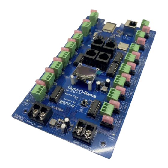
Page 4: Hardware Overview
Hardware Overview This section of the manual is meant to provide a base level tour of the hardware interfaces on the Aurora Core. Later in the manual, more details will be provided about these elements. - Page 5 The micro SD card slot is reserved for future functionality and is not currently used. 7. DMX Output Ports These ports allow the Aurora Core to send serial DMX commands to any DMX capable device, including LOR controllers. DMX Output and Long Range Receiver Communication Driver Chips These removable components are replaceable in the event of damage occurring from electrical surges or similar accidental electrical damage.
- Page 6 13. Power Input Connections There are 2 power banks on the Aurora Core, Ports 1-8 (left) and Ports 9-16 (right). The left (ports 1-8) power input is required to have power for the board to power up. Both left and right power banks can be fed either 5VDC or 12VDC.
-
Page 7: Getting Started - Connecting To A Network
If a device is not using DHCP on an ethernet network, it has to be told what IP address to use, which is typically called “static IP”. The Aurora Core is capable of being on a network with DHCP or using a static IP address. - Page 8 Isolated Example 1 Isolated Example 2...
- Page 9 In this scenario, DHCP is not present, so the Aurora Core is not “given” an address and will just default to its factory default static IP address, 192.168.1.50. This IP address will be displayed on the information screen as well as the designation that this is its static address.
- Page 10 2. Open Network Status selection. 3. Select Ethernet Properties. You will then see another window appear. Click “edit” under the IP Assignment area.
- Page 11 Change the drop down selection from Automatic (DHCP) to Manual (static). Click ON the IPv4 button.
- Page 12 These values can be different for more advanced network setups. 8. Hit save. Ensure that your Aurora Core ethernet port is connected to your computer's ethernet port or to the same switch/network. 9. Open LOR Control Panel and go to the Controller Setup tab. Click the option for...
- Page 13 Aurora Core. 11. Press Scan and your network will be searched for any available controllers. In this example, we only have a factory default, out of the box Aurora Core connected to the isolated ethernet network.
- Page 14 12. Clicking on the IP address 192.168.1.50 in the scan results will take you to the setup page of the Aurora Core. 13. Now you can decide to leave the Aurora Core on the 192.168.1.50 address or change it. We will talk more about network settings on the Aurora Core in another section.
-
Page 15: Part Of Your Existing Dhcp Network
Part of your Existing DHCP Network It is also an option to plug your Aurora Core into your existing ethernet network. Most wifi routers are set up to utilize DHCP to automatically assign IP addresses to devices. There are some potential issues with running your show with the below setup in terms of having it on the same network as your home and all of its devices, but it is a valid setup. - Page 16 In this scenario, as long as your computer is on the same network as the Aurora Core, the Aurora Core setup page can be accessed by either using the scanner in Controller Setup in Control Panel (same step as the previous section) or typing the IP address of the Aurora Core...
-
Page 17: Configuring Over Wifi
The Aurora Core also has the ability to allow configuration of the controller via its own wifi hotspot. The primary use of this feature is to allow direct connection to the Aurora Core from a mobile device no matter the status of the ethernet connection. - Page 18 Open the web browser on your device and enter the hotspot IP in the address bar and the configuration page will load. Having this page open will not affect the controller’s operation while running a show and this method of connecting can be used to check on the controller’s status during a show if you are within range of the controller.ome sections of the configuration page (Outputs) will only offer a simplified version without all options as the wifi hotspot configuration feature is not meant for performing full out of the box setup.
-
Page 19: Controller Setup - Web Interface
Controller Setup - Web Interface Once you have the Aurora Core powered up and successfully connected to your computer, it is time to set your controller settings for your specific use. Home Page The home page allows for navigation to all of the specific configuration pages. The gray row under the navigation tabs shows the IP address of the controller and the name of the controller. - Page 20 Clicking this option will download 1 file to your computer that contains a copy of all of the settings on your Aurora Core for backup purposes. It is always a good idea to keep a backup copy of your controller settings.
-
Page 21: Inputs
(170 pixels x 3 = 510). Most typical configurations on the Aurora Core will not require the Channels per Universe to be set to anything other than 510. The Channels per Universe value... - Page 22 See the below diagram for the correlation between Inputs configuration and network configuration in S6 Control Panel: In the networks tab in the Control Panel in S6, a successful Aurora Core configuration for the example of the default IP Address and universes is shown below. A green check mark signifies that the Control Panel can communicate with the Aurora Core, but the universe numbers that are configured to be sent to the Aurora Core must be properly defined.
- Page 23 Note: If using Art-Net, when adding the network in Control Panel, ensure that the “Adjust Art-Net universe” setting is OFF if using an Aurora Core.
-
Page 24: Outputs
Outputs This page is where the behavior of all output ports (16 pixel outputs, 2 DMX outputs, and 2 Long Range Receiver outputs) is configured. All E1.31/Art-Net commands that are sent to the Aurora Core are told where to go by the settings on this page. All settings that you configure on the output page of your controller will need to match the Channel settings for your props in your preview. -
Page 25: Column Details
The above image shows the default configuration of the Aurora Core - 150 pixels per port, 16 universes. Column Details Receivers Output ● Outputs 1-16 correspond to the 16 pixel output ports on the Aurora Core ● Outputs 17-24 correspond to any Long Range Receiver that are used ●... -
Page 26: Start Channel
Start Channel box for Output 1 and copy it to all other active outputs. Type ● The 16 pixel ports on the Aurora Core support any WS281X protocol pixels. The default value of the RGB order is “RGB” = Red, Green, Blue. If the color order of your pixels differs, the Type setting will allow for the proper setting of the color order for each port. -
Page 27: Count
Count ● This defines the total number of pixels connected to this output. ● If a pixel count that increases the universes needed to beyond what is defined on the Inputs tab, the box in question will turn RED ● The magic wand will copy the Count value from Output 1 and duplicate it to all other active outputs. -
Page 28: End Channel
● If a value for a given output causes the End Universe to not be able to be correctly calculated, an “X” will appear in this field. End Channel ● This value is calculated automatically based on what is configured for a given output for the Start Universe, Start Channel, and Count. -
Page 29: Start And End Nulls
“X” will appear in this field. Start and End Nulls ● This is a method to have the Aurora Core “ignore” pixels at the beginning/start of a string or at the end ○ Example: Count = 100, Start Nulls = 5. -
Page 30: Gamma
Gamma ● Gamma correction is an advanced setting, designed to adjust color values and how humans perceive color change and brightness levels. This option is available for users to experiment with if certain pixels are not giving the desired color output. ●... -
Page 31: Long Range Receivers
Long Range Receivers If using Long Range Pixel Receivers, enter the configuration information in the output rows 17-20 and 21-24. These number (port) ranges will match up the labeling on the Aurora Core for the 2 Long Range Outputs. Long Range Receivers work by the Aurora Core sending the pixel data only over a cat5/6 cable to a remote receiver, where the pixels are actually connected to. - Page 32 If more information is needed on Long Range Receiver setup, contact LOR (www.lightorama.com).
-
Page 33: Dmx Output
Note: If the channel count entered is higher than the Channels per Universe setting on the Input tab, the channels will automatically spill over into the next universe. In this example, any commands sent from your show to Universe 17, would be routed to the DMX1 Output on the Aurora Core:... -
Page 34: Testing
Testing The testing page allows for customized testing options. Note: If the test mode on the Aurora Core is active, all E1.31/Art-Net commands will be ignored, and the test mode will run. - Page 35 The light bulb button on the top left of the page will turn on test mode for whichever outputs are enabled for test mode (have the check marks). Turning on the test mode from the webpage is the same result as turning on the test mode from the test button on the board. Testing using the button on the board is achieved by holding the test button on the board down for 1 second.
- Page 37 The filter search bar can also be used to quickly find outputs to test. Isolating certain outputs in test modes can help track down issues during troubleshooting.
-
Page 38: Power
Power This page can be used to monitor how much power is being used by each port. Before using this feature for the first time, unplug all pixels from all ports, press the reset calibration button, then perform the calibration. Each port will now say 0mA and the feature can now be used. After plugging in lights and turning them on, you will start to see the live readout of how much power is being used:... - Page 39 The count pixel feature is able to automatically calculate the number of pixels hooked up to any of the 16 output ports. This feature works correctly with most pixels available on the market, but should be used only as a helpful feature.
-
Page 40: Network
Network The network page allows for control of the network settings for both the wired ethernet port and the wifi hotspot (reminder: wifi hotspot used for configuration only). The bold headers list what the current IP addresses are for both wired ethernet and wifi hotspot:... -
Page 41: Wired Ethernet Network
DHCP network. This name will not be used by LOR software at all. Wired Static IP ● This field is where you are able to manually set the IP address of the Aurora Core. The factory default Static IP Address is 192.168.1.50. If you have more than one ethernet... -
Page 42: Wifi Hotspot
255.255.255.0. ● Reminder: If you have the Aurora Core connected to a DHCP network, this field will not be used, as the Aurora Core will get a gateway address automatically. - Page 43 ● Reminder: Even if the password and/or hotspot name are changed, the QR code on the information screen on the Aurora Core will still allow you to scan and automatically connect to the hotspot (including automatically entering the passphrase into your...
-
Page 44: Update
Update This page is used to perform firmware updates for the Aurora Core. The current firmware version is shown on this page for reference when determining if a firmware update is needed. High-level firmware updates are performed on this page with .bin files on the LOR Firmware update webpage. - Page 45 8. Remove power to the Aurora Core to complete the process 9. Restore power to the Aurora Core. Watch the information screen on the board. As the board powers on, the on board information screen will momentarily show the version of...
-
Page 46: Hardware Details
Hardware Details This section will provide more in-depth details about the hardware interfaces on the Aurora Core. - Page 47 The fuse is blowing to protect the Aurora Core. ***Do not replace these fuses with any size larger than 4A as this could cause damage to occur to the Aurora Core board*** 2.
- Page 48 2. Press and hold the Factory Reset button. 3. Restore power to the Aurora Core (ensuring that at least the “Power 1-8” light is lit) while continuing to hold the Factory Reset button. 4. Continue holding the Factory Reset button for 10 seconds, then release.
- Page 49 4. Ethernet Port Used to connect the Aurora Core to an ethernet network switch or your computer’s ethernet port. This port must be connected to your computer running the show for the controller to function in your system during a show. This port also allows your computer to configure the controller in addition to the ability to configure the controller via wifi.
- Page 50 controllers. “ESTA” is used for the entertainment industry standard DMX wiring used in many widely available DMX devices. With the jumpers in LOR configuration, you are able to connect directly from an Aurora Core DMX output (with a standard cat5 or cat6 cable) to any DMX capable LOR products and send DMX commands to them.
- Page 51 Note: All 3 jumpers must be moved into the proper position for the wiring configuration to be changed. See examples below. DMX 1 and DMX2 both configured for ESTA: DMX 1 configured for ESTA and DMX 2 configured for LOR...
- Page 52 If all other features of the Aurora Core are working properly, but all of a sudden, one of the DMX or Long Range Receiver Outputs has stopped working, the cause may be that the driver chip has blown.
- Page 53 One method for chip removal is to use a very small flat head screwdriver and slowly pry the far ends up little by little until the chip is free. When inserting a new chip, be sure to insert the proper orientation, identified by the notch on the chip noted in the image below:...
- Page 54 Pixels connected to Long Range Receivers count as part of the 10,000 pixel total that is able to be controlled by the Aurora Core. In the Outputs tab of the web configuration page, you are able to configure what data gets sent to the long range receiver ports in the 17-20 and 21-24 section.
- Page 55 Press the test button momentarily to wake up the screen. A quick glance at the information screen can tell you if the Aurora Core is using a static IP address or a DHCP assigned IP address. The Hotspot IP (that you enter into your mobile device web browser when connected to the hotspot) is only shown on the information screen when a device is connected to the hotspot.
- Page 56 If all other features of the Aurora Core are working properly, but all of a sudden one or more of the pixel outputs has stopped working, the cause may be that the driver chip has blown.
- Page 57 LOR*** 13. Power Input Connections There are 2 power banks on the Aurora Core, Ports 1-8 (left) and Ports 9-16 (right). The left (ports 1-8) power input is required to have power for the board to power up. Both left and right power banks can be fed either 5VDC or 12VDC.
- Page 58 GND Terminal corresponds to the terminal typically labeled “-V” on the power supply. Two power supplies can be used (like above), especially in the situation of needing one side of the controller to be 5V and the other 12V. It is also fine to use 1 larger power supply connected to both 1-8 and 9-16 sides of the controller.
-
Page 59: Pixels Per Port
Unlike other LOR pixel controllers, there is not a pre-defined limit of pixels per port. The overarching limit of the Aurora Core is ~10,000 (58 universes) total RGB pixels. The per port limit is then defined by a few factors, the largest of which is the use of “power injection” on a continuous string(s) of pixels. -
Page 60: Example Configurations
Channels/Circuits 1-8 on the controller. For the purpose of this example, the Aurora Core will be at its default static IP address, 192.168.1.50 and we will assume that the diagram below is the entirety of our show. - Page 61 From a physical configuration standpoint, the jumpers for DMX1 have been verified to be in the LOR position: Let’s start with the Aurora Core configuration. The universe numbers were chosen randomly for this example to illustrate that depending on your setup, your universe numbers may not be sequential.
- Page 62 Let’s next take a look at the S6 Control Panel - Networks. Remember, the networks tab in the control panel for this Aurora Core must match/include everything in the Input tab. This is what it would look like. There will only be 2 entries for the same E1.31 controller...
- Page 63 Here is the prop definition for the 8 channel AC Arch. As expected, we are using DMX as the network type and Universe for all channels is 30. The reason that we are using channels 17-24 for the AC channels is because the Unit ID of the AC controller is set to ID 2 (See Appendix A for more information).
- Page 64 Core is configured to 100%. Note as well that we have Max channel set to 510 to match the Aurora Core setting in the Inputs tab, however the max channel setting is not at play here since this prop does not get above 300 channels.
- Page 65 Spinner 2 is configured to DMX, with a start Universe of 11 and start channel of 1. To fully utilize Universe channel spaces, this prop could have also been chosen to start at Universe 10, channel 301 and the Aurora Output configured similarly.
- Page 66 Finally, Spinner 3 is configured to DMX, with a start Universe of 12 and start channel of...
- Page 67 To fully check your end to end configuration, visit the Test Lights tab of the Control Panel and the Test Preview tab. This allows you to send commands from end to end to test that your preview is correctly set up to match how you have your lights physically hooked up.
-
Page 68: Appendix A - Lor Controllers And Dmx
Appendix A - LOR Controllers and DMX The addressing used in a LOR network is a little different than the addressing scheme used in DMX, however they are close enough that the LOR paradigm can be extended to DMX addressing. In a LOR network, regardless of the number of outputs (channels) a Unit has, it is assigned a single Unit ID (address). - Page 69 Connecting the LOR Unit to the DMX Universe LOR networks are usually wired using standard CAT5 (CAT5e) patch cables.The cables are wired straight through. To connect a LOR Unit to a DMX universe you will need an adapter. Most commonly, DMX hardware uses XLR connectors. LOR/DMX Adapter Pin Connections RJ45 Pin XLR Pin (3 Pin XLR)
Need help?
Do you have a question about the Aurora Core and is the answer not in the manual?
Questions and answers