Shure AD3 - Plug-On Transmitter Manual
- User manual (23 pages) ,
- User manual (11 pages)
Advertisement
- 1 Introduction
- 2 Features
- 3 Included Components
- 4 Optional Accessories
- 5 AD3 Transmitter Overview
- 6 Setup
- 7 Setting the AA Battery Type
- 8 Transmitter Controls
- 9 Menu Overview
- 10 Home Screen Display
- 11 Locking the Interface
- 12 IR Sync
- 13 Setting the Frequency Manually
- 14 Updating Firmware
- 15 RF Mute
- 16 Safe Start
- 17 Input Overload
- 18 Tone Generator
- 19 Matching Audio Levels with Offset
- 20 Menu Item Descriptions
- 21 Utilities Menu
- 22 Troubleshooting
- 23 Contact Customer Support
- 24 Specifications
- 25 Documents / Resources
![]()
Introduction
The Shure AD3 plug-on transmitter transforms any microphone into an advanced, portable Axient Digital AD Series wireless microphone, delivering impeccable audio quality and RF performance, wide-tuning, and encryption features. Compatible with Axient Digital AD4D and AD4Q receivers in Standard or High Density modes, AD3 features a custom, fast, and secure XLR connector design, support for both conventional AA and Shure SB900-series rechargeable battery options, and simple, userfriendly controls and menus. The AD3 is housed in a lightweight, rugged, metal chassis and is designed to resist sweat, moisture, and debris.
Features
Performance
- 20 Hz to 20 kHz range with flat frequency response
- Automatic input staging optimizes gain setting
- AES 256-bit encryption-enabled for secure transmission
- >120 dB dynamic range
- 100 meter (300 feet) line-of-sight operating range
- Selectable modulation modes optimize performance for spectral efficiency
- Standard – optimal coverage, low latency
- High density – dramatic increase in max system channel count
- Built-in tone generator and RF markers to facilitate walk-testing
- Switchable Power Levels = 2/10/35 mW (region dependent)
Design
- Locking XLR connector
- OLED display with easy-to-navigate menu and controls
- Rugged metal construction
- Menu and power lockout
Power
- Over 8 hours continuous use with Shure rechargeable battery
- Shure lithium-ion rechargeable battery provides extended battery life, precision metering, and zero memory effect
- External power and charging over USB-C
Included Components
| AA alkaline batteries (2) | 80B8201 |
| USB-A to USB-C cable | 95A39299 |
| Zipper bag | 95D2313 |
| Pouch with belt clip | 95A44910 |
Optional Accessories
| SB900B rechargeable lithium-ion battery | SB900B |
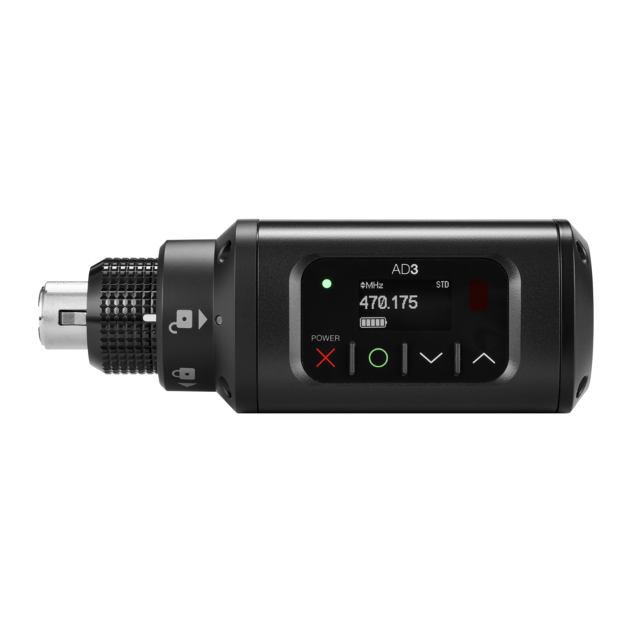
AD3 Transmitter Overview
- Display
View menu screens and settings. Press any control button to activate the backlight. - Infrared (IR) port
Align with the receiver IR port during an IR Sync for automated transmitter tuning and setup. - Control buttons
Use to navigate through parameter menus and to change settings. - Power switch
Hold the X button to power the unit on or off. - Enter button
Press to enter menu screens and confirm menu changes. - Power LED
- Green = Unit is powered on
- Red = Low battery, or battery error
- Audio LED
Red, yellow, and green LEDs indicate average and peak audio levels.
The LED will turn red when the limiter is engaged. - USB-C port
Supplies power or charges Shure rechargeable battery. LED indicates charging status when connected to a power supply.- Red = Charging
- Green = Full charge
- Yellow = Not charging
- Battery compartment
Requires two AA batteries or Shure rechargeable battery. - AA battery adapter
Use to secure AA batteries. Remove when using a Shure rechargeable battery. - XLR connector
Connection point for wired microphones, cables, and boom poles, among other things. - Locking ring
To release the XLR connector, turn the ring counterclockwise and push in. - Pouch
Provides additional grip and protection for the transmitter. - Belt clip
Holds transmitter and microphone securely for hands-free carrying.


Setup
- Slide the tab on the side of the transmitter to open the battery door.
- Install the batteries.
- AA batteries: Place batteries (note polarity markings) and AA adapter as shown below and close the door.
- Shure rechargeable battery: Place battery as shown below (note polarity markings). Remove the AA adapter and close the door to secure the battery.

Note: If using AA batteries, set the battery type to ensure the transmitter's battery status indicator is accurate.
- Press and hold X to turn on the transmitter.
- Select the appropriate input pad or boost to avoid overloading the audio input our add boost to low-output sources: Audio > Pad
- 12 12 dB: Use with high output sources, such as line levels and point-to-point applications.
- Off (default): Use with typical microphones.
- +12 dB: Use with low output sources.
- Plug the transmitter into an XLR microphone or the output of an audio device.

Note: If you remove or replace the batteries without turning the transmitter off, the device will turn on again when the batteries are replaced.
Setting the AA Battery Type
To ensure accurate display of transmitter runtime, set the battery type to match the battery you have installed.
Note: If a Shure rechargeable battery is installed, selecting a battery type is not necessary and the battery type will display Shure.
- Navigate to Utilities and select Battery.
- Use the ▼▲ buttons to select the installed battery type:
- Alkaline = Alkaline
- NiMH = Nickel Metal Hydride
- Lithium = Lithium Primary
- Press O to save.


Shure Rechargeable Battery
Shure SB900 series lithium ion batteries offer a rechargeable option for powering the transmitters. Batteries charge to 50% capacity in 1 hour and reach full charge within 3 hours.
Single chargers and multiple bay chargers are available to recharge the Shure batteries.

Only charge Shure rechargeable batteries with a Shure battery charger.
Shure SB900B Runtime
| 2 mW | 10 mW | 35 mW |
| 8+ hours | 8+ hours | 5+ hours |
Note: Phantom power, RF output and the impedance of the connecting device can impact battery life.
Checking Battery Info
When using a Shure rechargeable battery, the receiver and transmitter home screens display the number of hours and minutes remaining.
- Detailed information for the battery is displayed Battery menu of the transmitter: Utilities > Battery
- Battery: The chemistry type of for the installed battery (Shure, Alkaline, Lithium, NiMH)
- Battery Time to Full (only appears when Shure rechargeable battery is being externally charged): Time remaining until battery is fully charged
- Battery Life: Indicates remaining battery runtime
- Charge: Percentage of charge capacity
- Health: Percentage of current battery health
- Cycle Count: Total of the number of charging cycles for the installed battery
- Temperature: Battery temperature reported in Celsius and Fahrenheit
![]()

Power Over USB
When operated with AA batteries, or without batteries, the AD3 transmitter can be powered by connecting the USB-C port on the bottom of the transmitter to a suitable power source.
When a Shure rechargeable battery is inserted, the USB connection can power the transmitter while simultaneously charging the battery.
Important Tips for Care and Storage of Shure Rechargeable Batteries
Proper care and storage of Shure batteries results in reliable performance and ensures a long lifetime.
- Always store batteries and transmitters at room temperature
- Ideally, batteries should be charged to approximately 40% of capacity for long-term storage
- Periodically clean the battery contacts with alcohol to maintain ideal contact
- During storage, check batteries every 6 months and recharge to 40% of capacity as needed
For additional rechargeable battery information, visit www.shure.com.
Note: A Battery Hot warning indicates that transmitter battery needs to cool off. Otherwise, the transmitter will shut down. Let the device cool down and then consider swapping the transmitter battery to continue operation.
Identify any possible external heat sources to the transmitter and operate the transmitter away from those external heat sources.
All batteries should be stored and operated away from external heat sources in reasonable temperature conditions for best performance.
AA Batteries and Transmitter Runtime
Transmitters are compatible with the following AA battery types:
- Alkaline
- Nickel Metal Hydride (NiMH)
- Lithium Primary
A 5 segment battery indicator representing the charge level of the transmitter battery is displayed on the screens of the transmitter and receiver. The following table contains the approximate remaining transmitter runtime in hours: minutes.
Alkaline Batteries
| Battery Indicator | Battery Runtime (hours: minutes) | |||
| UHF | 1.x | |||
| 2 mW/10 mW | 35 mW | 2 mW /10 mW | 30 mW | |
 | 8:00 to 6:00 | 3:30 to 3:00 | 5:30 to 4:15 | 3:45 to 3:00 |
 | 6:00 to 4:00 | 3:00 to 2:00 | 4:15 to 3:00 | 3:00 to 2:15 |
 | 4:00 to 1:45 | 2:00 to 1:30 | 3:00 to 1:45 | 2:15 to 2:00 |
 | <1:45 | <1:30 | <1:45 | <2:00 |
 | <0:45 | <0:45 | <0:45 | <0:45 |
 | <0:15 | <0:15 | <0:15 | <0:15 |
Transmitter Controls
Use the controls to navigate menus and update settings.

| X | Hold button to turn transmitter power on and off. Acts as a 'back' button to return to previous menus or pa rameters without confirming a value change. |
| O | Enters menu screens and confirms parameter changes |
| ∨∧ | Use to scroll through menu screens and to change parameter values |
Tip: Hold the ∧ button while powering on to enter safe start mode.
Menu Overview
Menu Map

Tips for Editing Menu Parameters
- To access the menu options from the home screen, press O. Use the arrow buttons to see additional menus and parame ters.
- A menu parameter will blink when editing is enabled
- To increase, decrease, or change a parameter, use the arrow buttons
- To save a menu change, press O
- To exit a menu without saving a change, press X
Home Screen Display
The home screen shows transmitter information and status.
There are four pieces of information that you can choose to see on the home screen. Use the arrow buttons to select one of the following choices:

Name
Frequency Setting
Group (G) and Channel (C)
Device ID
The following icons indicate transmitter settings:
 | Battery runtime in hours and minutes or bar display |
 | Key: Displayed when encryption is enabled |
 | Lock: Displayed when controls are locked. Icon flashes if you attempt to access a locked control (power or menu). |
 | STD: Standard Transmission Mode |
 | HD: High Density Transmission Mode |
Locking the Interface
Lock transmitter interface controls to prevent accidental or unauthorized changes to parameters. The lock icon appears on the home screen when a lock is enabled.
- From the Utilities menu, navigate to Locks and select one of the following lock options:
- None: The controls are unlocked
- Power: The power switch is locked
- Menu: The menu parameters are locked
- All: The power switch and menu parameters are locked
- Press O to save.
Tip: To quickly unlock the transmitter menu, press O and select None.
IR Sync
Use IR Sync to form an audio channel between the transmitter and receiver.
Note: The receiver band must match the band of the transmitter.
- Select a receiver channel.
- Tune the channel to an available frequency using group scan or manually turn to an open frequency.
- Power on the transmitter.
- Press the SYNC button on the receiver.
- Align the IR windows between the transmitter and the receiver so that the IR LED illuminates red. When complete, Sync Success! appears. The transmitter and receiver are now tuned to the same frequency.
![]()

Note: Any change to the encryption status on the receiver (enabling/disabling encryption) requires a sync to send the settings to the transmitter. New encryption keys for the transmitter and receiver channel are generated on every IR sync, so to request a new key for a transmitter, perform an IR sync with the desired receiver channel.
Setting the Frequency Manually
The transmitter can be manually tuned to a specific group, channel, or frequency.
- Navigate to the Radio menu and select Freq.
- Scroll to select G: and C: to edit the group and channel, or select the frequency parameter (MHz). When editing the fre quency, press O once to edit the first 3 digits, or twice to edit the last 3 digits.
- Use the ∧∨ buttons to adjust the group, channel, or frequency.
Press O to save, and then press X when finished.
![]()

Updating Firmware
Firmware is embedded software in each component that controls functionality. Periodically, new versions of firmware are developed to incorporate additional features and enhancements. To take advantage of design improvements, you can upload and install new versions of the firmware by using the Shure Update Utility. The Shure Update Utility is available for download from http://www.shure.com/.
Firmware Versioning
When performing an update, first download firmware to the receiver, and then update transmitters to the same firmware version to ensure consistent operation.
The firmware numbering for Shure devices uses the following format: MAJOR.MINOR.PATCH.BUILD (e.g., 1.2.21.1). At a minimum, all devices on the network (including transmitters), must have the same MAJOR and MINOR firmware version numbers (e.g., 1.2.x).
Updating the Transmitter
- Download the firmware to the receiver.
- Access the following menu from the receiver: Device Settings > Tx Firmware Update.
- Align the IR ports between the transmitter and the receiver. IR ports must be aligned for the entire download, which can take 50 seconds or longer.
Tip: The red alignment LED will turn on when the alignment is correct. - Press ENTER on the receiver to begin the download to the transmitter. The receiver will display the progress of the update as a percentage.
RF Mute
RF mute prevents transmission of the audio by suppressing the RF signal while the transmitter remains powered-on. The home screen displays RF Muted in this mode.

- From the Radio menu, navigate to Output.
- Choose one of the following options:
- On: RF signal is active
- Mute: RF signal is disabled
- Press O to save.
Note: Turning the transmitter off and on or replacing the battery will restore Output to On.
Safe Start
Power on in safe start mode to prevent interference with other devices. Hold the ^ button while powering on your device until the Safe Start menu appears.

Safe Start menu options:
- RF: Mute or On
- Locks: None, Pwr, Menu, All
- Phantom: Off, +12V, +48V
Use the navigation buttons to make changes.
Tip: To exit the Safe Start menu, push X.
Note: Previous settings for locks, RF, and phantom power will be retained when the transmitter is powered on in safe start mode.
Input Overload
The Tx Overload message appears when the audio input experiences a high level signal. The audio LED turns red as an additional indicator of an overload. Reduce the input signal or enable the input pad to remove the overload condition.
Tip: To enable the input pad, navigate to Audio > Pad and select 12 dB.

Tone Generator
The transmitter contains an internal tone generator that produces a continuous audio signal. The tone is helpful when conducting a sound check or for troubleshooting the audio signal chain. The level of the tone is adjustable from -60 dB to 0 dB and the frequency can be set to 400 Hz or 1000 Hz.
Tip: Always start with the level set to -60 dB to avoid overloading speakers or headphones.
- From the Audio menu select Tone Gen.
- Set the frequency to 400 Hz or 1000 Hz.
- Select Level and use the arrow buttons adjust the value between -60 dB and 0 dB.
Turn off the tone by selecting Off from the menu or by cycling the transmitter power.

Matching Audio Levels with Offset
When linking two or more transmitters to a receiver, there may be a difference in volume levels between microphones or instruments. If this occurs, use the Offset function to match the audio levels and eliminate audible volume differences between transmitters. If using a single transmitter, set Offset to 0 dB.
- Turn on the first transmitter and perform a sound check to test the audio level. Turn off the transmitter when finished.
- Turn on the second transmitter and perform a sound check to test the audio level. Repeat for any additional transmit ters.
- If there is an audible difference in the sound level between the transmitters, navigate to the Offset menu (Audio > Offset) in the transmitter to increase or decrease the Offset in realtime to match the audio levels.
![]()

Menu Item Descriptions
Radio Menu
Freq
Press the O button to enable editing of a group (G:) channel (C:) or frequency (MHz). Use the arrow buttons to adjust the values. To edit the frequency, press the O button once to edit the first 3 digits, or twice to edit the second 3 digits.
Power
Higher RF power settings can extend the range of the transmitter.
Note: Higher RF power settings decrease battery runtime.
Output
Sets the RF output to On or Mute.
- On: RF signal is active
- Mute: RF signal is inactive
Audio Menu
Phantom
Adds phantom power for condenser microphones. Select +12V or +48V as required by the microphone.
Input Pad/Boost
Adjust the pad to avoid overloading the audio input or add a boost to low output sources. Choose between 12 dB, Off (default), and +12dB.
- 12 dB: Use with high output sources, such as line levels and point-to-point applications.
- Off (default): Use with typical microphones.
- +12 dB: Use with low output sources.
HP Filter
High-pass filter. Scroll up to turn on the filter and set the low-frequency rolloff in Hz; scroll all the way down to turn off. Range: 40 Hz to 240 Hz.
Polarity
Selectable polarity assignment for the audio input connector:
- Pos: Positive pressure on microphone diaphragm produces positive voltage on pin 2 (with respect to pin 3 of XLR output) and the tip of the TRS output on the receiver.
- Neg: Positive pressure on microphone diaphragm produces negative voltage on pin 2 (with respect to pin 3 of XLR output) and the tip of the TRS output on the receiver.
Offset
Adjust Offset level to balance mic levels when using two transmitters or when assigning multiple transmitters to receiver slots. Adjustment range: -12 dB to +21 dB.
Tone Gen
Tone generator. Transmitter will generate a continuous test tone:
- Freq: The tone can be set to 400 Hz or 1000 Hz.
- Level: Adjusts the output level of the test tone.
Utilities Menu
Device ID
Assign a device ID of up to 8 characters.
Locks
Locks the transmitter controls and power switch.
- None: The controls are unlocked
- Power: The power switch is locked
- Menu: The menu parameters are locked
- All: The power switch and menu parameters are locked
Marker
When enabled, press O to drop a marker in Wireless Workbench.
Battery
Displays battery information:
- Battery Life: Runtime reported in bar display and time (hours: minutes)
- Battery Time to Full (only appears when Shure rechargeable battery is being externally charged): Time remaining until battery is fully charged
- Charge: Percentage of charge capacity
- Health: Percentage of current battery health
- Cycle Count: Total of the number of charging cycles for the installed battery
- Temperature: Battery temperature reported in Celsius and Fahrenheit
About
Displays the following transmitter information:
- Model: Displays the model number
- Band: Displays the tuning band of the transmitter
- FW Version: Installed firmware
- HW Version: Hardware version
- Serial Num: Serial number
Reset All
Restores all transmitter parameters to factory settings.
Troubleshooting
| Issue | See Solution... |
| No sound | Power, Cables, Radio Frequency, or Encryp tion Mismatch |
| Faint sound or distortion | Gain, Cables |
| Lack of range, unwanted noise bursts, or dropouts | Radio Frequency (RF) |
| Cannot turn transmitter off or change frequency settings, or can't pro- | Interface Locks |
| gram receiver | Interface Locks |
| Encryption Mismatch message | Encryption Mismatch |
| Firmware Mismatch message | Firmware Mismatch |
| Transmitter Battery Hot message | Tx Battery Hot |
| Antenna Fault Red LED | RF |
| Handheld transmitter shuts down during use | Clean Battery Contacts |
Power
Make sure that the receiver and transmitter are receiving sufficient voltage. Check the battery indicators and replace the transmitter batteries if necessary.
Gain
Adjust the system gain on the front of the receiver. Ensure the output level on the back of the receiver corresponds to the mic/ line input setting of the mixing console, amplifier, or DSP.
Cables
Check that all cables and connectors are working correctly.
Interface Locks
The transmitter and the receiver can be locked to prevent accidental or unauthorized changes. A locked feature or button will produce the Locked screen on the LCD panel or the lock icon will flash on a transmitter.
Encryption Mismatch
Re-sync all receivers and transmitters after enabling or disabling encryption.
Firmware Mismatch
Paired transmitters and receivers must have the same firmware version installed to ensure consistent operation. See Firmware topic for firmware update procedure.
Tx Battery Hot
If the transmitter battery does not cool off, the transmitter will shut down. Let the device cool down and then consider swapping the transmitter battery to continue operation.
Identify any possible external heat sources to the transmitter and operate the transmitter away from those external heat sources.
All batteries should be stored and operated away from external heat sources in reasonable temperature conditions for best performance.
Radio Frequency (RF)
RF LEDs
If neither blue RF Diversity LED is illuminated, then the receiver is not detecting the presence of a transmitter.
The orange RF Signal Strength LEDs indicate the amount of RF power being received. This signal could be from the transmitter, or it could be from an interfering source, such as a television broadcast. If more than two of the orange RF LEDs are still illuminated while the transmitter is off, then that channel may be experiencing interference, and you should try a different channel.
The red RF LED indicates RF overload. Overloads have the potential to cause interference in multiple system installations. If you are experiencing an overload, turn off the receiver to see if it is causing interference with other components.
The numerical channel select button also turns red to indicate interference.
- Dim red = Channel is not selected, experiencing interference
- Bright red = Channel is selected, experiencing interference
Compatibility
- Perform a Scan and Sync to ensure the transmitter and receiver are set to the same group and channel.
- Look at the band label on the transmitter and make sure the receiver is set to the same band.
Reducing Interference
- Perform a group or channel scan to find the best open frequency. Perform a sync to transfer the setting to the transmitter.
- For multiple systems, check that all systems are set to channels in the same group (systems in different bands do not need to be set to the same group).
- Maintain a line of sight between transmitter and receiver antennas.
- Move or point receiver antennas away from metal objects or other sources of RF interference (such as LED walls, comput ers, digital effects, network switches, network cables and Personal Stereo Monitor (PSM) wireless systems).
- Eliminate RF overload (see below).
Increasing Range
If the transmitter is more than 6 to 60 m (20 to 200 ft) from the receiver antenna, you may be able to increase range by doing one of the following:
- Reduce interference (see above).
- Increase transmitter RF power level.
- Use Normal mode instead of High Density mode.
- Use an active directional antenna, antenna distribution system, or other antenna accessory to increase RF range.
Eliminating RF Overload
If you see the red RF LED on a receiver, try the following:
- Reduce the transmitter RF power level
- Move the transmitter further away from the receiver—at least 6 m (20 ft)
- If you are using active antennas, reduce antenna or amplifier gain.
- Use omnidirectional antennas
Antenna Faults
The Antenna Fault red LED indicates a short circuit condition or excessive load at an antenna port.
- Check antennas and cables for damage
- Ensure that antenna ports are not overloaded
- Check antenna bias voltage setting. Turn off voltage if using passive antennas.
Clean Battery Contacts
Clean the battery contacts with an electrical contact cleaner designed for gold contacts and safe on plastics.
Contact Customer Support
Didn't find what you need? Contact our customer support to get help.
Specifications
Mic Offset Range
12 to 21 dB (in 1 dB steps)
Battery Type
Shure SB900 series Rechargeable Li Ion or LR6 AA batteries 1.5 V
Battery Runtime
@ 10 mW
| Shure SB900B | > 8 hours |
| alkaline | > 7 hours |
Dimensions
126 mm x 44.5 mm x 44.5 mm (5.0in. x 1.8in. x 1.8 in.) H x W x D
Weight
| Without Battery | 240 g (8.0 oz.), |
| with AA batteries | 263 g |
| with Shure rechargeable battery | 280 g |
Housing
Cast Metal
Operating Temperature Range
-10°C (-14°F) to 50°C (122°F)
Note: Battery characteristics may limit this range.
Storage Temperature Range
-40°C (-40°F) to 74°C (165°F)
Note: Battery characteristics may limit this range.
Audio Input
Connector 3-pin female XLR
Configuration
balanced
Impedance
| Pad-12 dB | 26.64 kΩ |
| 0 dB | 6.64 kΩ |
| Boost12 dB | 6.64 kΩ |
Maximum Input Level
1 kHz at 1% THD
| Pad-12 dB | 21 dBV |
| 0 dB | 9 dBV |
| Boost12 dB | 3 dBV |
Preamplifier Equivalent Input Noise (EIN)
System Gain Setting ≥ +20
-115 dBV, A weighted, typical
Phantom Power
+48 V(7 mA maximum), +12 V(15 mA maximum)
High Pass Filter
Two-pole (12 dB per octave), cut off frequency selectable from 40 to 240 in 20 Hz increments
RF Output
Antenna Type
Dipole
Impedance
50 Ω
Occupied Bandwidth
<200 kHz
Channel-to-Channel Spacing
| Standard Mode | 350 kHz |
| High Density Mode | 125 kHz |
varies by region
Modulation Type
Shure Axient Digital Proprietary
Power
2 mW, 10 mW, 35 mW
See Frequency Range and Output Power table, varies by region
Specific Absorption Rate (SAR)
< 0.12 W/kg
Frequency Range and Transmitter Output Level
| Band | Frequency Range ( MHz) | RF Power ( mW)*** |
| G53 | 470 to 510 | 2/10/35 |
| G54 | 479 to 565 | 2/10/20 |
| G55† | 470 to 636* | 2/10/35 |
| G56†† | 470 to 636 | 2/10/35 |
| G57 | 470 to 616* | 2/10/35 |
| G62 | 510 to 530 | 2/10/35 |
| G63 | 487 to 636 | 2/10 |
| H54 | 520 to 636 | 2/10/35 |
| K53 | 606 to 698* | 2/10/35 |
| K54△ | 606 to 663** | 2/10/35 |
| K55 | 606 to 694 | 2/10/35 |
| K56◇ | 606 to 714 | 2/10/35 |
| K57△ | 606 to 790 | 2/10/35 |
| K58 | 622 to 698 | 2/10/35 |
| L54 | 630 to 698 | 2/10/35 |
| L60 | 630.125 to 697.875 | 2/10/35 |
| P55 | 694 to 703, 748 to 758, 803 to 806 | 2/10/35 |
| R52 | 794 to 806 | 2/10 |
| JB | 806 to 810 | 2/10 |
| X51 | 925 to 937.5 | 2/10 |
| X55 | 941 to 960 | 2/10/35 |
| X56††† | 960 to 1000 | 2/10/35 |
*With a gap between 608 to 614 MHz.
**With a gap between 608 to 614 MHz and a gap between 616 to 653 MHz.
***Power delivered to the antenna port.
†Operation mode varies according to region. In Brazil, High Density mode is used. The maximum power level for Peru is 10mW.
††Limited to 10mW for Vietnam.
†††Only in UK; F-variant only.
△Output power limited to 10 mW above 608 MHz.
◇Korea defines power as conducted (ERP) which is 1dB less then declared in table.
K55 606-694 MHz
| Country Code | Frequency Range |
| A, B, BG, CH, CY, CZ, D, DK, EST, F | * |
| FIN, GB, GR, H, HR, I, IRL, IS, L, LT | * |
| M, N, NL, P, PL, RO, S, SK, SLO, TR | * |
| all other countries | * |
* This equipment may be capable of operating on some frequencies not authorized in your region. See Licensing Information.
G56 470-636 MHz
| Country Code | Frequency Range |
| A, B, BG, CH, CY, CZ, D, DK, EST, F | * |
| FIN, GB, GR, H, HR, I, IRL, IS, L, LT | * |
| M, N, NL, P, PL, RO, S, SK, SLO, TR | * |
| all other countries | * |
* This equipment may be capable of operating on some frequencies not authorized in your region. See Licensing Information.
K57 606-790 MHz
| Country Code | Frequency Range |
| A, B, BG, CH, CY, CZ, D, DK, EST, F | * |
| FIN, GB, GR, H, HR, I, IRL, IS, L, LT | * |
| M, N, NL, P, PL, RO, S, SK, SLO, TR | * |
| all other countries | * |
* This equipment may be capable of operating on some frequencies not authorized in your region. See Licensing Information.

- Battery packs may explode or release toxic materials. Risk of fire or burns. Do not open, crush, modify, disassemble, heat above 140°F (60°C), or incinerate.
- Follow instructions from manufacturer
- Only use Shure charger to recharge Shure rechargeable batteries
![]()
Danger of explosion if battery incorrectly replaced. Replace only with same or equivalent type.- Never put batteries in mouth. If swallowed, contact your physician or local poison control center
- Do not short circuit; may cause burns or catch fire
- Do not charge or use battery packs other than Shure rechargeable batteries
- Dispose of battery packs properly. Check with local vendor for proper disposal of used battery packs.
- Batteries (battery pack or batteries installed) shall not be exposed to excessive heat such as sunshine, fire or the like
- Do not immerse the battery in liquid such as water, beverages, or other fluids.
- Do not attach or insert battery with polarity reversed.
- Keep away from small children.
- Do not use abnormal batteries.
- Pack the battery securely for transport.
 | If water or other foreign objects enter the inside of the device, fire or electric shock may result. Do not attempt to modify this product. Doing so could result in personal injury and/or product failure. |
 | Never disassemble or modify the device, as failures may result. Do not subject to extreme force and do not pull on the cable or failures may result. Keep the microphone dry and avoid exposure to extreme temperatures and humidity. |
Note: Use only with the included power supply or a Shure-approved equivalent.
Shure Europe GmbH
Department: Global Compliance
Jakob-Dieffenbacher-Str. 12
75031 Eppingen, Germany
Phone: +49-7262-92 49 0
Fax: +49-7262-92 49 11 4
Email: EMEAsupport@shure.de

Documents / Resources
References
Download manual
Here you can download full pdf version of manual, it may contain additional safety instructions, warranty information, FCC rules, etc.
Advertisement


Need help?
Do you have a question about the AD3 and is the answer not in the manual?
Questions and answers