Table of Contents
Advertisement
Quick Links
Advertisement
Table of Contents

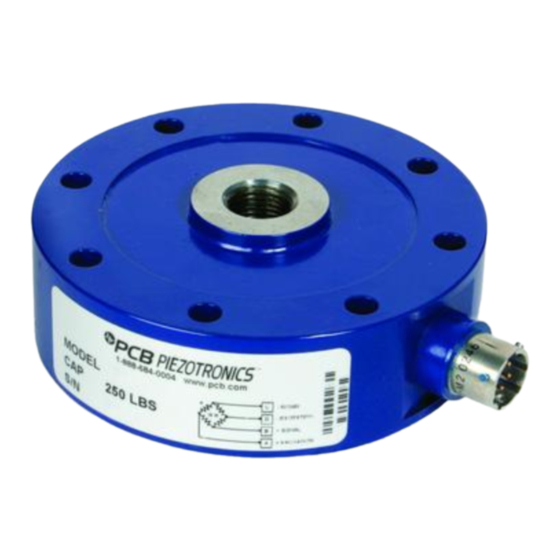
Summary of Contents for PCB Piezotronics 1204-13A
- Page 1 Model 1204-13A LOW PROFILE LOAD CELL Installation and Operating Manual For assistance with the operation of this product, contact PCB Piezotronics, Inc. Toll-free: 800-828-8840 24-hour SensorLine: 716-684-0001 Fax: 716-684-0987 E-mail: info@pcb.com Web: www.pcb.com...
- Page 2 Returning Equipment – Following the equipment to PCB Piezotronics for these procedures will insure that your repair. User servicing or repair is not returned materials are handled in the recommended and, if attempted, may most expedient manner.
- Page 3 PCB Piezotronics, Inc. Warranty – All equipment and repair 3425 Walden Ave. services provided by PCB Piezotronics, Depew, NY 14043 USA Inc. are covered by a limited warranty Toll-free: (800) 828-8840 against defective...
-
Page 4: Table Of Contents
GENERAL PURPOSE LOW PROFILE LOAD CELL OPERATION MANUAL TABLE OF CONTENTS 1.0 INTRODUCTION........................2 2.0 SAFETY PRECAUTIONS ....................2 3.0 OVERVIEW .......................... 2 3.1 Dimensions ............................2 3.2 Standard Components ........................3 3.3 Optional Components ........................3 4.0 MECHANICAL INSTALLATION ..................3 4.1 Mounting Bases ..........................3 4.2 Mounting Load Cell to a Standard Base or Custom Fixture .............3 4.3 Threaded Tension Rods........................4 4.4 Mounting Optional Connector Protectors..................4... -
Page 5: Introduction
GENERAL PURPOSE LOW PROFILE LOAD CELL OPERATION MANUAL 3.1 Dimensions 1.0 INTRODUCTION The following figure and tables give the general outline General purpose low profile load cells manufactured by PCB dimensions of the general purpose low profile load cells with Load &... -
Page 6: Standard Components
GENERAL PURPOSE LOW PROFILE LOAD CELL OPERATION MANUAL 3.2 Standard Components NOTE: The use of the tension base greatly increases the performance of the low profile load cell. The following figure describes the standard components of the general purpose low profile load cells. 4.0 MECHANICAL INSTALLATION Load Cell The following mechanical installation instructions should be... -
Page 7: Threaded Tension Rods
GENERAL PURPOSE LOW PROFILE LOAD CELL OPERATION MANUAL Table 4 – Tension Base Installation Torque Values Bolt Size Part Number Installation Torque 1/4-28x1 3/4 100-8011-10 15-17 LbFt (180-204 LbIn) 100-8082-20 75-80 LbFt (900-960 LbIn) 3/8-24x2 1/4 100-8011-30 120-130 LbFt (1440-1560 LbIn) 1/2-20x3 1/2 3/4-16x4 1/2 100-10026-40... -
Page 8: Electrical Installation
GENERAL PURPOSE LOW PROFILE LOAD CELL OPERATION MANUAL 5.2 Cable & Grounding Considerations Proper grounding and shielding is required to prevent electrical noise in strain gage load cell measuring systems. The cable must be shielded twisted pairs with a drain wire. Cable shields must be grounded only at one end, for example, on the instrument or control system ground. -
Page 9: Measured Output
GENERAL PURPOSE LOW PROFILE LOAD CELL OPERATION MANUAL 6.1.1 Measured Output 7.0 MOMENT COMPENSATION The applied load starting at zero is measured in five When an eccentric axial load is increments to full scale. Output (mV/V) is measured at each applied to a load cell that is not Primary increment. -
Page 10: Shunt Calibration Description
GENERAL PURPOSE LOW PROFILE LOAD CELL OPERATION MANUAL 9.1 Resistor Value Aircraft Quality Steel Alloy General purpose low profile load cells have a nominal 4.0 Steel Safety Factor > 2.5 Aluminum Alloy mV/V full scale output for non-fatigue rated and a nominal 2.0 Aluminum Safety Factor ≈... -
Page 11: Trouble Shooting
GENERAL PURPOSE LOW PROFILE LOAD CELL OPERATION MANUAL are not allowed to migrate into devices that are not Check bridge balance. hermetically sealed. Such devices should only be wiped with a damp cloth, and never be submerged or have liquids poured 10. -
Page 12: Rma / Purchase Order
GENERAL PURPOSE LOW PROFILE LOAD CELL OPERATION MANUAL Standard calibration certificates list five force points ascending and one point descending in both tension and compression. Additional data points are available at extra cost upon request. Certificate information includes tabulated measurement variable data zero balance, bridge input/output resistance, computer nonlinearity and hysteresis, static error band (SEB) calculations and entries abilities and traceability statements. - Page 13 Model Number Revision: NR LOW PROFILE LOAD CELL 1204-13A ECN #: 41624 Performance ENGLISH OPTIONAL VERSIONS [6][7] Measurement Range 50 klbf 222 kN Optional versions have identical specifications and accessories as listed for the standard model [3][1] Sensitivity(± 10 %)(RO) 4.0 mV/V...
- Page 14 PCB Load & Torque Inc. claims proprietary rights in REVISIONS the information disclosed hereon. Neither it nor any reproduction thereof will be disclosed to others without 12X 3/8-24 X 2.25 [57.2] 12 POINT FLANGE BOLT DESCRIPTION the written consent of PCB Load and Torque Inc. 12X 3/8-24 UNF-2B .88 [22.4] ADD FIELD NOTE 2...


Need help?
Do you have a question about the 1204-13A and is the answer not in the manual?
Questions and answers