Table of Contents
Advertisement
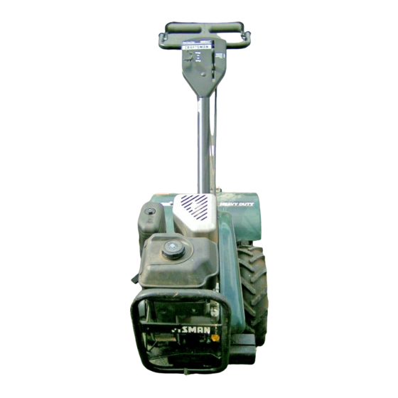
Owner's Manual
[RAFTSMAN +
6.0 HP
17 INCH TINE WIDTH
REAR TINE WITH
COUNTER ROTATING TINES
TILLER
Model No
917.293310
• Safety
_
• Assembly
/_
• Operation
I (_._
'"°n enonce/
• Espanol
_
• Repair Parts
CAUTION:
Read and followall
Safety Rules and Instructions
101efore operatingthis equipment
_ears, Roebuck and Co., Hoffman Estates, IL 60179
Advertisement
Table of Contents

Subscribe to Our Youtube Channel
Related Manuals for Craftsman 917.29331


Summary of Contents for Craftsman 917.29331
- Page 1 Owner's Manual [RAFTSMAN + 6.0 HP 17 INCH TINE WIDTH REAR TINE WITH COUNTER ROTATING TINES TILLER Model No 917.293310 • Safety • Assembly • Operation I (_._ '"°n enonce/ • Espanol • Repair Parts CAUTION: Read and followall Safety Rules and Instructions 101efore operatingthis equipment _ears, Roebuck and Co., Hoffman Estates, IL 60179...
- Page 2 • If this Craftsman Tiller is used for commercial or rental purposes, this Warranty applies for only thirty (30) days from the date of pumhase. Warranty service is available by returning the Craftsman power mower to the nearest Sears service center/department this product is in use in the United States.
- Page 3 Allow the engine to cool before storing in any enclosure. • Always refer to the operator's guide instructions for important details if the tiller is to be stored for an extended _pedod. CAUTION: Always disconnect spark plug wire and place wire where it cannot...
-
Page 4: Specifications
These accessories were available when the tiller was purchased. able at most Sears Retail outlets and Service Centers, [epair parts for you when you provide the model number of your tiller. ENGINE SPARK PLUG... - Page 5 Your new tiller has been assembled at the factory with exception of those parts left unassembled for shipping purposes. To ensure safe and proper operation of your tiller all pads and hardware you assemble must be tightened securely. Use the cor- rect tools as necessary to insure proper tightness.
-
Page 6: Install
• Rotate handle assembly down. rear carriage bolt first, with head of bolt o-n L.H. side of tiller and loosely assem- ble Iocknut. Loosen Handle Lock Lever to Move • Insert pivot bolt in front part of plate and tighten. - Page 7 (neutral) position. • Tilt tiller forward by lifting handle. Separate cardboard cover from leveling shield. • Rotate tiller handle to the right and pull tiller out of carton. Attach this end to shift lever -..-..._._..._ _-.-Attach this End To shift _...
- Page 8 KNOW YOUR TILLER READ THIS OWNER'S MANUAL AND SAFETY RULES BEFORE TILLER. Compare the illustrations with your tiller to familiarize yourself with the location of vari- ous controls and adjustments, Save this manual for future reference. Throttle Control Drive Control Bar...
- Page 9 The operation of any tiller can result in foreign objects thrown into the eyes, which can result in severe eye damage. Always wear safety glasses or eye shields before starting your tiller and while tilling. We recommend a wide vision safety mask over spectacles or standard safety glasses.
- Page 10 (both sides). Retighten nuts. TO TRANSPORT _.CAUTION: Before lifting or transport- ing, allow tiller engine and muffler to cool. Disconnect spark plug wire. Drain gaso- line from fuel tank. AROUND THE YARD • Release the depth stake pin. Move the depth stake down to the top hole for transporting the tiller.
- Page 11 Tines will not readily penetrate dry, hard soil which may contribute to excessive bounce and difficult handling of your tiller. Hard soil should be mois- tened before tilling; however, extremely wet soil will =ball-up" or clump during till- Do not ing.
-
Page 12: Cultivating
©0,000 00!000 00[000 00lO:O TINE SHEAR The tine assemblies on your tiller are secured to the tine shaft with shear pins from rob- (See "TINE REPLACEMENT" Service and Adjustments section of this manual). If the tiller is unusually overloaded or... - Page 13 1 - Change more often when operating under a heavy load or k_high ambietlt t_ture_. 2 - Service more often when operating in dirty or dusty co_dl_s. GENERAL RECOMMENDATIONS The warranty on this tiller does not cover items that have been subjected tO opera- tor abuse or negligence. To receive full value from the warranty, th e operator must maintain tiller as instructed in this manual.
- Page 14 Change the oil after every 50 hours of operation or at least once a year if the tiller is not used for 50 hours in one year. Check the crankcase oil level before start- ing the engine and after each five (5) hours of continuous use.
- Page 15 • Retighten handle lock lever securely after adjusting. MUFFLE R Do not operate tiller without muffler. Do not tamper with exhaust system. Damaged mufflers or spark an'asters could create a fire hazard. Inspect periodicallyand re- place if necessary. If your engine is...
- Page 16 When mounting tires, unless beads are seated, overinflation can cause an explosion. • Maintain 20 pounds of tire pressure. _tire w_essures are not equal, tiller will pull to one side. • Keep tires free of gasoline or oil which can damage rubber.
- Page 17 _CAUTION: Tines are sharp. Wear gloves or other protection when handling tines. A badly worn tine causes your tiller to work harder and dig more shallow. Most impor- tant, worn tines cannot chop and shred organic matter as effectively nor bury it as deeply as good tines.
- Page 18 ENGINE Maintenance, repair, or replacement of the emission control devices and systems, which are being done at the customers expense, may be performed by any non- road engine repair establishment or indi- vidual. Warranty repairs must be per- formed by an authorized engine manufac- turer's service outlet.
- Page 19 Allow the engine to cool before storing in any enclosure. TILLER • Clean entire tiller (See =CLEANING" the Maintenance section of this manual). • Inspect and replace belts, if necessary (See belt replacement...
- Page 20 PROBLEM CAUSE Will not start 1. Out of fuel. 2. Engine not "CHOKED" properly. 3. Engine flooded. 4. Dirtyair cleaner. 5. Water in fuel. 6. Clogged fuel tank. 7. Loose spark plug wire, 8. Bad spark plug or improper gap. 9.
- Page 21 1. Ground too wet. Soil balls up or clumps Engine runs but "l]necontrol is not engaged, tiller won't move V-belt not correctlyadjusted. V-belt is off pulley(s). Engine runs but "13iling t oo deep. labors when tilling Throttle control not propedy adjusted.
- Page 22 TILLER - ,,MODEL NUMBER 917.293310 HANDLES PART DESCRIPTION 164743 Throttle,Control 141406 Gdp, Handle 110673X Grommet, Handle 127254X Bar,Drive Control Assembly 6712J Cap, Vinyt 137119 Panel, Control 110641X Bushing,Split 71191008 *Screw, Pan Head #10-24 72010520 *Bolt,5/16-18 x2-1/2 110646X Handle, Grip STD624003 •Clip, Hairpin...
- Page 23 TILLER - - MODEL NUMBER MAINFRAME, LEFT SIDE PART DESCRIPTION STD541431 Nut, Keps 5/16-18 STD551137 "Washer, Lock 3/5 STD541037 "Nut, Hex 3/8-16 165710 Shield,Inner Belt:Guard 154734 Screw ShiftLaver 110111X Lever, Shift STD532505 *Bolt,Cardage 1/4-20 x 1/2 Gr. 5 8700J Ptata, Shift Indicator...
- Page 24 11 STD624003 *Clip, Hairpin 12 126875X Rivet, Drilled 13 5015.1 128952 795R Tire Valve 14 STD541431 *Nut, Keps 5/16-18 15 ... Engine, (See Breakdown) Craftsman Model No. 121432-0124-E1 STANDARD HARDWARE -- PURCHASELOCALLY NOTE: Allcomponent dimensions giveninU.S.inches. 1 inch= 25,4 mm...
- Page 25 TILLER - - MODEL NUMBER TRANSMISSION PART DESCRIPTION 165728 TransmissionAssembly(Includes Key Nos. 2-52) 165729 Gearcase, L.H. w/Bearing(includes Key No. 4) 161963 Gasket, Gearcese 5020J Beadng, Needle 1370H Washer, Thrust 5/9 _ 1,10 x 1/32 137335 Pinion, Input 145101 Shaft, input...
- Page 26 TILLER - - MODEL TINE SHIELD /0=_... PART DESCRIPTION 98000129 Nut, Flange 5/16-18 161415X558 Shield, Side, Outer L. H, 8393J Pin, Stake, Depth 12000036 Ring, Klip STD533107 *Bolt, Carriage 5/16-18 x 3/4 Gr 5 8394J Spring 8392J Bracket,Latch 109230X Spring, Depth Stake 124289X558 Shield,"nne...
- Page 27 TILLER - - MODEL TINE ASSEMBLY PART DESCRIPTION 4459J "13ne, Outer, L.H. 132673 Pin, Shear 6554J line, Inner, L.H. 163552 *Clip, Hairpin 132727 Assembly,Hub and Plate, L.H. 73610600 Nut, Hex 3/8-24 STD551137 *Washer,Lock3/8 74610616 Bolt.Rex 3/8-24 x 1 NUMBER 917.293310...
- Page 28 TILLER - - MODEL NUMBER DECALS PART 166213 145023 166134 166133 137538 120431X 102180X 157984 120075X 163094 162215 166138 166854 167155 166007 917.293310 DESCRIPTION Decal, Logo Decal, Logo Decal, Logo Decal, Description Decal, Caution, Drive Control Decal, Hand Placement Decal, Shift Indicator...
- Page 29 TILLER - - MODEL NUMBER 917.293310 ENGINE, BRIGGS & STRATTON - - MODEL NUMBER 121432-0124-E1 I 1010 LABEL KIT I "k REQUIRES SPECIAL TOOLS TO INSTALL.. SEE REPAIR INSTRUCTION MANUAL [ 1058 OWNER'S MANUAL I 33 40 ,022 _j 13.._...
- Page 30 TILLER - - MODEL NUMBER 917.293310 ENGINE, BRIGGS & STRATTON - - MODEL NUMBER 121432-0124-E1 634A _) 111 II 186_ 124 _,...
- Page 31 TILLER - - MODEL NUMBER 917.293310 ENGINE, BRIGGS & STRATTON - - MODEL NUMBER 121432-0124-E1 1005 305A_...
- Page 32 TILLER - - MODEL NUMBER 917.293310 ENGINE, BRIGGS & STRATI'ON - - MODEL NUMBER 121432-O124-E1 281 _ 663 J) 22211 188_ 621<1q_ 3ss_ 838_ 863A_ 819 _ 883 _;_ 373 _3...
- Page 33 TILLER - - MODEL NUMBER 917.293310 ENGINE,BRIGGS& STRATTON .. - MODEL NUMBER 121432-0124-E1 358 GASKET SET '°_' "N_ 163 0 "__!' 977 CARBURETOR GASKET SET 121 CARBURETOR KIT 11°° 9 634_ 11o_ 127_ ,.0 'Y 1033 VALVE OVERHAUL KIT •...
- Page 34 TILLER -- MODEL NUMBER 917.293310 'ENGINE, BRIGGS & STRATFON PART DESCRIPTION 690045 CylinderAssembly 399269 Bushing,Cylinder 299819 * Seal, Oil 693643 Head, Cylinder 273489 &'Jr Gasket, CylinderHead 693647 Tube, Breaker 692549 "JrGasket, Crankcase 95049 Screw,Cylinder Head 94916 Plug, OilDrain 693403 Crankshaft...
- Page 35 TILLER - - MODEL ENGINE, BRIGGS & STRATTON - - MODEL NUMBER 121432-0124-E1 PART DESCRIPTION 263131 Cop, Valve 221535 Clamp, Casing 693407 Panel, Control 692595 Strap, Muffler 693593 Muffler,Exhaust 693621 Housing,Blower 692577 Screw, P anel 305A 690960 Screw, BlowerHousing 306B 692557 Screw, Rocker Cover 3/8"...
- Page 36 Forthe repairor replacement p artsyou need delivered directlyto your home Call 7 am - 7 pro,7 daysa week 1-800-366-PART (1-800-366-7278) Para ordenar piezas con entrega domicilio - 1-800-659-7084 For in-house major brand repair service Call 24 hours a day, 7 days a week 1-800-4-REPAIR (1-800-473-7274) Para...
Need help?
Do you have a question about the 917.29331 and is the answer not in the manual?
Questions and answers