Advertisement
Available languages
Available languages
Quick Links
Owner's Manual
ICRRFTSMIIN'J
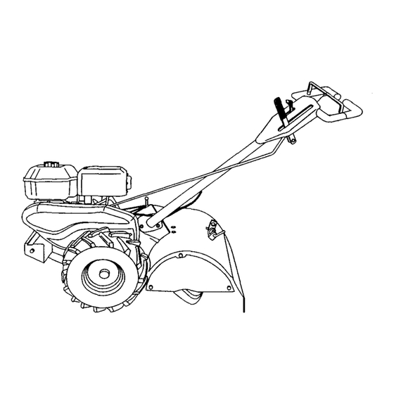
TILLER
5.5 HP, 14 Inch Tine Width
Rear Tine with
Counter Rotating Tines
Model No.
917.293472
I_
his product has a low emission engine which operates
differently
from previously
built engines. Before you start the
engine, read and understand
this Owner's Manual.
CAUTION:
Read and follow all Safety
Rules and Instructions before
operating this equipment.
Sears, Roebuck and Co., Hoffman Estates, II 60179 U.S.A.
Visit our Craftsman website:www.sears.com/craftsman
Advertisement

Related Manuals for Craftsman 917.293472


Summary of Contents for Craftsman 917.293472
- Page 1 Owner's Manual. CAUTION: Read and follow all Safety Rules and Instructions before operating this equipment. Sears, Roebuck and Co., Hoffman Estates, II 60179 U.S.A. Visit our Craftsman website:www.sears.com/craftsman...
-
Page 2: Table Of Contents
• If this Craftsman Tiller is used for commemial or rental purposes, this Warranty applies for only thirty (30) days from the date of purchase. - Page 3 • Never attempt to make any adjustments • Never operate the tiller without good while the engine (motor) is running visibility or light. (except where specifically recommend- • Be careful when tilling in hard ground. ed by manufacturer). The tines may catch in the ground and propel the tiller forward.
-
Page 4: Safety Rules
PRODUCT SPECIFICATIONS CUSTOMER RESPONSIBILITIES • Read and observe the safety rules. GASOLINE 3 QUARTS • Follow a regular schedule in maintain- UNLEADED CAPACITY: ing, caring for and using your tiller. REGULAR • Follow the instructions under the SAE 30 OIL (API-SF-SJ): "Customer Responsibilities"... - Page 5 Your new tiller has been assembled at the FRONT factory with exception of those parts left unassembled for shipping purposes. ensure safe and proper operation of your tiller all parts and hardware you assemble must be tightened securely. Use the correct tools as necessary to insure RIGHT proper tightness.
-
Page 6: Assembly
UNPACKING CARTON ACAUTION: Be careful of exposed staples when handling or disposing of "UP" Position cartoning material. IMPORTANT: When unpacking and lever to hold assembling tiller, be careful of exposed Loosen Handle Lock staples when handling or disposing of Lever to Move cartoning material. - Page 7 INSERT CABLE CLIP Shift Lever Hairpin Indicator • insert plastic cable clip into hole on the back of handle column. Push cables Shift Rod into clip. Handle Column Cables Cable Clip REMOVE TILLER FROM CRATE CONNECT SHIFT ROD 1. Insert end of shift rod farthest from 1.
- Page 8 These symbols may appear on your Tiller or in literature suppliedwith the product. Learn and understand their meaning. KNOW YOUR TILLER READ THIS OWNER'S MANUALAND SAFETY RULES BEFORE OPERATING YOUR TILLER. Compare the illustrations with your tiller to familiarize yourself with the location of various controls and adjustments.
-
Page 9: Operation
The operation of any tiller can result in foreign objects thrown into the eyes, which can result in severe eye damage. Always wear safety glasses or eye shields before starting your tiller and while tilling. We recommend a wide vision safety mask over spectacles or standard safety glasses. HARD TO SHIFT GEARS HOW TO USE YOUR TILLER Know how to operate all controls before... - Page 10 • For approximate capacity see "PROD- TURNING UCT SPECIFICATIONS" on page 4 of 1. Release the drive control bar. this manual. All oil must meet A.P.I. 2. Move throttle control to "SLOW" Service Classification SF-SJ. position. • For cold weather operation you should 3.
- Page 11 TILLING HINTS TO START ENGINE _aaCAUTION, Until you are accustomed to &CAUTION: Keep drive control bar in ndling your tiller, start actual field use =DISENGAGED" position when starting with throttle in slow position (mid-way engine. between "FAST" and "IDLE"). When starting engine for the first time or if •...
- Page 12 CULTIVATING • Place blocks under right hand side of tiller and remove hairpin clip and clevis pin from right hand wheel. 2. Move wheel outward approximately inch until hole in inner wheel hub ADJUST WHEELS lines up with inner hole in axle. Replace clevis pin and hairpin clip on inside of wheel and remove blocks•...
-
Page 13: Maintenance Schedule
MAINTENANCE SCHEDULE 1 - Change more often when operating under a heavy load or _n high ambient temperatures. 2 - Service moreoften when operatingin dirty or dustyconditions. LUBRICATION CHART GENERAL RECOMMENDATIONS The warranty on this tiller does not cover * Throttle Control items that have been subjected to operator abuse or negligence. - Page 14 5. Refill engine with oil. See "CHECK _kCAUTION:Disconnect spark plug wire ENGINE OIL LEVEL" in the Operation before performing any maintenance section of this manual. (except carburetor adjustment) to prevent accidental starting of engine. Prevent firest Keep the engine free of grass, leaves, spilled oil, or fuel.
- Page 15 Knob MUFFLER Do not operate tiller without muffler. Do not Cover\ tamper with exhaust system. Damaged mufflers or spark arresters could create a fire hazard. Inspect periodically and replace if necessary. If your engine is equipped with a spark arrester screen assembly, remove every 50 hours for cleaning and inspection.
- Page 16 TIRE CARE ._=._,..======_ B I/t Guard "_r-'_'_. . " _/jHex _CAUTION: When mounting tires, unless //_/_//and beads are seated, overinflation can _./_ Washer cause an explosion. _._-----"_ (Located • Maintain 20 pounds of tire pressure. _._; Behind tire pressures are not equal, tiller will pull to one side.
- Page 17 TINE REPLACEMENT • To maintain the superb tilling perfor- mance of this machine the tines should _kCAUTION: Tines are sharp. Wear be checked for sharpness, wear, and gloves or other protection when handling bending, particularly the tines which tines. are next to the transmission. If the gap A badly wom tine causes your tiller to between the tines exceeds 3-1/2...
- Page 18 TO ADJUST CARBURETOR ENGINE The carburetor has been preset at the Maintenance, repair, or replacement of factory and adjustment should not be the emission control devices and sys- necessary. However, engine perfor- tems, which are being done at the mance can be affected by differences in customers expense, may be performed fuel, temperature, altitude or load.
-
Page 19: Storage
NOTE: Fuel stabilizer is an acceptable Immediately prepare your tiller for storage at the end of the season or if the unit will alternative in minimizing the formation of not be used for 30 days or more. fuel gum deposits during storage. Add _I_CAUTION: Never store the tiller with stabilizer to gasoline in fuel tank or... - Page 20 PROBLEM CAUSE CORRECTION 1. Fill fuel tank. Will not start 1. Out of fuel. 2. See "TO START ENGINE" in 2. Engine not "CHOKED" properly. the Operation section. 3. Wait several minutes before 3. Engine flooded. attempting to start. 4. Dirty air cleaner. 4.
- Page 21 PROBLEM CAUSE CORRECTION Engine 1. Low oil level/dirty oil. 1. Check oil level/change oil. overheats 2. Clean engine air screen. 2. Dirty engine air screen. 3. Dirty engine. 3. Clean cylinder fins, air screen, muffler area. 4. Remove and clean muffler. 4.
- Page 22 • Si la Cultivadora Craftsman se usa para fines de arriendo, esta garantia se aplica solamente pot treinta (30) dfas a partir de la fecha de compra.
- Page 23 MANTENIMIENTO • Tenga mucho cuidado cuando opere o cruce entradas para autombviles de dpio, ALMACENAMIENTO senderos o caminos. Est6 alerta en Io que • Mantenga los accesodos y aditamentos de se refiere a los peligros escondidos o al la m_quina en buenas condiciones para el tr&fico.
- Page 24 RESPONSABIUDADES DEL CLIENTE ESPEClFICAClONES DEL PRODUCTO • Lea y observe las reglas de saguridad. CAPACIDAD DE 3 CUARTOS • Siga un programa regular de mantenimiento, GASOLINA: SIN PLOMO, REGULAR cuidado y uso de su culttvadora. ACEITE(API-SF-SJ): SAE 30 (SOBRE 32°F) •...
- Page 25 Su cultivadora nueva ha sido montada en la PARTE DELANTERA fi_bdca, con la axcepci6n de aquellas partes qua se dejaron sin montar por razonas de envfo. Para asegurarse qua la cultivadora LADO LADO operard en forma segura y adecuada, todas IZQUIERDO DERECHO las partes y los articulos de ferreteria qua...
- Page 26 DESEMPAQUE DE LA CAJA CART(_N Conjuntodel mango _PRECAUCI6N: Tenfa cuidado con las posocl6n"Arriba" grapas expuestas cuando maneje o deseche Apriete la palancade los materiales de la caja de cart6n. cierradel mangopara IMPORTANTE: Cuando desempaque y monte sujetarla la cultivadora, tenga cuidado de no estirar o enredar los cables.
- Page 27 INSERCI6N DE LA ABRAZADERA Abrazaderade Horqunla Indicadorde la CABLE Palancade Cambio • Inserte la abrazadera del cable de pldstico Vadllade Cambio dentro del agujero en la parte trasera de la columna del mango. Empuje los cables dentro de la abrazadera. Columna del Mango Cables...
- Page 28 Estos sfmbolos pueden apareser sobre su cultivadora en la literature propomlonada con el producto, aprenda y comprenda sus significados. CONOZCA SU CULTIVADORA LEA ESTE MANUAL DEL DUEI_IO Y LAS REGLAS DE SEGURIDAD ANTES DE OPERAR CULTIVADORA Compare las ilustraciones con su cultivadora para familiarizarse con la ubicaci6n de los...
- Page 29 La operacibn de cualquier cultivadora puede hacer que salten objetos extrafios anteojos de seguddad o protecciones para los ojos antes de hacer arrancar su cultivadora o mientras estd labrando con 611a. Recomendamos el uso de la entro de sus ojos, Io que puede producir dafios graves en 6stos. Siempre use m&scara de seguridad de visibn amplia, para uso sobre los espejuelos o anteojos de seguddad estdndar.
- Page 30 REVISION DEL NIVEL DEL ACEITE DEL GIRO MOTOR Suelte la barra de control de la impulsi6n. El motor en su unidad ha sido enviado desde Mueva el control de la aceleracibn a la posici6n de =LENTO" (SLOW). la fdbdca Ileno con aceite de calidad para el verano SAE 30.
- Page 31 _PRECAUCI6N: Llene el estanque de AVISO: A mucha altura (sobre 3000 pies) o en combustible hasta dentro de 1/2 pulgada de la climas fdos (debajo de 40 ° F [4 ° C]) puede qua la mezcla del combustible del carburador parte superior para evitar los darrames y para necasite ajuste, para obtanar el major permitir que se expanda el combustible.
- Page 32 CULTIVO • Ponga bloques debajo del lado derecho de la cultivadora ¥ remueva la abrazadara horquilla y la clavija de hoi'quilla de la rueda del lado derecho. Mueva la rueda hacia afuera, aproximadamente 1 pulgada, hasta que el agujero en el cubo de la rueda interior se AJUSTE DE LAS RUEDAS PARA...
- Page 33 MANTENIMIENTO LLENE I_AS FECHAS DE MEDIDA "_ _%_"Q_"_"Q_'/_/O_Q1 SERVIcIoQUE COMPLETEREGULARSU FECHAS SERVIClO Revisar el nivel del aceite del motor Cambiar el aceite del motor 111_.21 Aceitar los puntos de pivot° Inspeccionar el supresor del silenciador Inspeccionar la rejilla de aim IJmplar/cambiar el cartucho del fUtro de air°...
- Page 34 _PRECAUCl6N: Desconecte el alambre de Remuava e! tap6n del dep6slto de relleno la bujfa antes de dar mantenimlento (excepto de aceite. Tenga cuidado de no permitir por el ajuste del carburador) para evitar qua el que la mugre entre al motor. motor arranque por accidente.
- Page 35 SlLENCIADOR - Tomillo de la base No opere la cultivadora sin el silenciador. No Cubieda_ manipulee el sistema de escape, Los silenciadores o los amortiguadores de chispas daSados pueden crear un peligro de incendio. Inspecci6nelos pedbdicamente y cdmbielos si Atetas del es necesado.
- Page 36 CUIDADO DE LAS LLANTAS Pmtecci6nde la correa _PRECAUCI6N: Cuando monte las Ilantas, a _rca Hexagonal menos que los talones estdn asentados, si se • y amndela inflan demasiado se puede producir una (Ublcadasdetras explosi6n. • Mantenga 20 libras de presi6n en las Ifantas. de la Ilanta) Si la presi6n de las Ilantas no es la misma, la culUvadora va a tirar hacia un lado.
- Page 37 CAMBIO DE BRAZOS • Pare que esta rndquina pueda mantener un rendimiento excelente en el labrado, se _PRECAUCI6N: LOS brazos son afilados. deben revlsar los brazos pare vedficar si Use guantes u otra protecci6n cuando maneje los brazos. estdn afilados, desgastados o doblados, especialmente los que se encuentran al Si hay un brazo muy desgastado su lado de la transmisi6n.
- Page 38 MOTOR Cable del tomillode sujecl6n El mantenimiento, la reparaci6n, o el Cable de la reemplazo de cualquier dispositivos o sistemas del control de la emisi6n, los cuales Aceleraci6n,_ "_ sean hechos al costo del cliente, pueden ser realizados por cualquier individuo o establecimiento de reparaci6n de motor.
- Page 39 AVISO: El estabilizador de combustible es una Inmediatamente prepare su cultivadora para el almacenamiento al final de la temporada o si la altema_va aceptable para reducir a un mfnimo unldad no se va a usar por 30 dfas o m_.s. la formaci6n de dep6sitos de goma en el 4_kPRECABCl0N: Nunca almacene la...
- Page 40 PROBLEMA CAUSA Correcci6n No arranca Sin combustible. 1. Llene el estanque de combustible. Motor sin la =ESTRANGU- 2. Vea "PARA ARRANCAR MOTOR" en la seccibn de LACION" (CHOKE) adecuada. Operacibn. Motor ahogado. 3. Espere varios minutos antes de tratar de arrancar. Filtro de aire sucio.
- Page 41 CAUSA PROBLEMA CORRECCI_N Falta de fuerza 10.Rejilla de aim del motor sucia. 10. Limpie la rejilla de aire del motor. 11 .Silenciador sucio/taponado. 11. Limpie/cambie el silenciador. 12. Carburador desajustado. 12. Haga los ajustes necesados. 13. Mala compresibn. 13.Contacto con su cenb'o de servicio Sears o con un otro centro de servicio cualificado.
- Page 42 TILLER -- MODEL NUMBER 917.293472 HANDLES PART PART DESCRIPTION DESCRIPTION 180634 Throttle, Control STD541437 Nut, Crownlock 3/8-16 19131611 Washer 13/32x I x 11Ga. 141406 Grip, Handle 110673X Grommet, Handle 109228X Lever, Lock, Handle 150258 Handle, Assemble 127254X Bar, Ddve Control Assembly 6712J Cap, Vinyl 165197...
- Page 43 TILLER - - MODEL NUMBER 917.293472 MAINFRAME, LEFT SIDE PART PART DESCRIPTION DESCRIPTION STD541431 Nut, Keps Flange 5/16-18 STD624003 Clip, Hairpin STD551137 Washer, Lock 3/6 165501X558 Guard, Belt STD541037 132801 Belt, V Nut, Hex 3/8-16 170127 Shield, Inner Belt Guard 104679X Pulley, Idler 154734...
- Page 44 102190X Tire 102332 Bracket,Reinforcement 150750 102173X 795R Tire Valve CounterWeight,R,H. STD551137 Washer, Lock 3/8 Engine, (See Breakdown) Craftsman Model No. 120402- STD541037 Nut, Hex 3/8-16 0213-E1 74760524 Bolt, Hex 5/16-18 x 1-1/2 STD624003 7192J TieCable Clip,Hairpin 126875X Rivet,Ddned NOTE: All component dimensions given In U.S,inches.
- Page 45 TILLER -- MODEL NUMBER 917.293472 TRANSMISSION KEY PART PART DESCRIPTION DESCRIPTION 18O677 TransmissionAssembly(Includes 106388X Spacer 0.70 x 1.00 x 1.150 Key Nos. 2-52) 102121X Sprocketand Gear Assembly 180627 Gearcase, L.H. w/Bearing 102112X Shaft, Reduction(2nd) (IncludesKey No. 4) 102101X Screw, Whiz, Lock5/16-18 x 3-1/2 161963 Gasket, Gearcase 154355...
- Page 46 TILLER -- MODEL NUMBER 917.293472 TINE SHIELD PART PART DESCRIPTION DESCRIPTION STD541037 Nut, He)( 3/8-16 73900500 Nut, Lock Hex Flange 5/16-18 Unc 102156X Stake, Depth 8393J Pin, Stake, Depth 74930632 Bolt, Hex 3/8-16 x 2 12000036 Ring, Klip STD533107 Bolt, Carriage 5/16-18 x 3/4 Gr 5 4440J Hinge...
- Page 47 TILLER -- MODEL NUMBER 917.293472 TINE ASSEMBLY KEY PART PART DESCRIPTION DESCRIPTION 74610616 Bolt, Hex 3/8-24 x 1 4459J Tine, Outer, L.H. 4460J Tine, Outer, R.H. 132673 Pin, Shear 132722 Assembly, Hub and Plate, R.H. 6554J Tine, Inner, L.H. 6555J Tine, Inner, R.H.
- Page 48 TILLER -- MODEL NUMBER 917.293472 DECALS PART DESCRIPTION 176738 Decal, ServiceCNTRL PNL 176736 Decal, Belt Guard 137538 Decal, Caution,DriveControl 120431X Decal, HandPlacement 102180X Decal, Shift Indicator 166138 Decal,OperationIntek 167156 Decal, B & S Intek 120075X Decal,Waming,RotatingTines 157984 Decal,Tine, Shield,CounterRotatingTines 171078 Decal,Rewind Intek 162215 Decal,Tine, Shield,WarningDom...
- Page 49 TILLER - - MODEL NUMBER 917.293472 ENGINE, BRIGGS & STRATTON - - MODEL NUMBER 120402-0213-E1 I+e91 635_ 914A'_ 307 _I_ 15AQ 22_' , 1019 LABEL KIT , 746_ I 1058 OWNER'S MANUAL I...
- Page 50 TILLER -- MODEL NUMBER 917.293472 ENGINE, BRIGGS & STRATTON - o MODEL NUMBER 120402-0213-E1 365_) 6921 186_ 108 _ 276._ .ZJ276_ 276_ _/_163 9_CARBUR_OR GASK_SET If"61 276©I 633A_ 121 CARBURETOR OVERHAUL KIT llr L 2,sol 127_ 633_ 633A_ I 51 _-_'_ 358 ENGINE GASKET SET 1022_ 666_...
- Page 51 TILLER -- MODEL NUMBER 917.293472 ENGINE, BRIGGS & STRATTON - - MODEL NUMBER 120402-0213-E1 265_ 2221 427® ,,3_ ° _s8_ 883_:_ 717 _.,.I. 334_ 971 i'...
- Page 52 TILLER - - MODEL NUMBER 917.293472 ENGINE, BRIGGS & STRATTON - - MODEL NUMBER 120402-0213-E1 65 _ I 1036 EMISSIONS LABEL 305 _' 1095 VALVE GASKET SET...
- Page 53 TILLER - - MODEL NUMBER 917.293472 ENGINE, BRIGGS & STRATTON - - MODEL NUMBER 120402-0213-E1 PART PART DESCRIPTION DESCRIPTION 693811 Cylinder Assembly 691636 Screw (Throttle Valve) 690024 Shaft-Throttle 299819 693643 Head-Cylinder 398185 Kit-Idle Speed 2 Seal-Oil (Magneto Side) 695166 • Gasket-Cylinder Head 691242 _ Pin-Float Hinge...
- Page 54 TILLER - - MODEL NUMBER 917.293472 ENGINE, BRIGGS & STRATTON - - MODEL NUMBER 120402-0213-E1 PART PART DESCRIPTION DESCRIPTION 693610 Shield-Cylinder 692566 Gear-Idler 690345 Screw (Cylinder Shield) 694258 Retainer 690662 Nut (Flywheel) 694544 Stud (Rocker Arm) 695711 Armature-Magneto 693583 Guard-Muffler 691061 Screw (Armature Magneto) 690661...
- Page 56 For repairof majorbrandappliances In your own home... no matterwhomade it,no matterwhosoldit] 1-800-4-MY-HOME _ Any,n_ dayorr_t (U.SA =_d Canada) (1-800-469.4663) W_RI/m Forrepairof carry-in products likevacuums,lawnequipment, a nd elecbonics, c allfor the nearestSears Partsand Repair Center. 1-800-488-1222 Anyth_e, day orright ( U.S.A. only) www.seam.com Forthe replacement parts,accessories and owner'smanuals thatyou needtodo-it-yourself, callSears PadsDirectS"!
Need help?
Do you have a question about the 917.293472 and is the answer not in the manual?
Questions and answers