Advertisement
Quick Links
QUICK ASSEMBLY INSTRUCTIONS
1
Connect paddle wheel circuit wire to faceplate
2
Connect the (2) 9V batteries
3
Install 9V batteries into meter body
4
Secure face plate to meter body
and ensure you do not pinch any cables
5
Install the (4) 10-32 bolts and slightly snug
to tightness
HFM3_Assembly_Installation_120623
INSTALLATION GUIDELINES
This page details mounting and installation guidelines for the Dura-Meter
High Flow paddle wheel meter. These are location and installation guidelines.
This is not a troubleshooting guide for mechanical/electrical issues.
About 95% of the flow metering issues are
traceable back to the following 5 simple principles.
1
THE FLOW RATE MUST BE WITHIN THE RECOMMENDED RANGE
FOR THE PIPE SIZE THE METER IS INSTALLED ON.
All flow meters all have a minimum flow rate they will measure for each pipe size. No flow meter
reads down to 0. This lower limit is a result of the flow velocity not containing enough momentum
to keep the paddle wheel spinning. At some point the flow velocity drops and the paddle no longer
spins linearly with respect to the flow rate. This is the lowest flow rate the meter can accurately
measure. The meter may indicate flow rates below this value but will contain a large inaccuracy. At
some point the flow velocity becomes too low and the meter will indicate 0, even though there is
still flow.
The bottom line – if you don't have an adequate flow rate you need to either reduce the pipe
diameter or find a different flow meter. You won't get satisfactory results trying to monitor flows
below the recommended minimum value.
3" HIGH-FLOW DURA-METER
3" HIGH-FLOW DURA-METER
™
™
®
Advertisement

Related Manuals for DURA DURA-METER DP-HFM2


Summary of Contents for DURA DURA-METER DP-HFM2
- Page 1 HFM3_Assembly_Installation_120623 3” HIGH-FLOW DURA-METER ™ INSTALLATION GUIDELINES This page details mounting and installation guidelines for the Dura-Meter ® High Flow paddle wheel meter. These are location and installation guidelines. This is not a troubleshooting guide for mechanical/electrical issues. About 95% of the flow metering issues are traceable back to the following 5 simple principles.
- Page 2 THE PIPE MUST BE FULL OF FLUID AT ALL TIMES The pipe must be completely full of liquid! This is particularly an issue when the meter is installed on pipes that have a downward flow direction. Vertical pipes with a downward flow are the most prone to this issue.
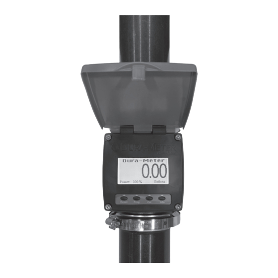
- Page 3 HIGH - FLOW DURA - METER ™ The meter will turn ON with any button press or when fluid passes through the meter. It will turn OFF when not in use. Use buttons to navigate the four main menus; Reset, Program, Calibration, Info. The buttons correspond to the on screen indicators.
- Page 4 CALIBRATION NOTE: Use a primed system. Verify your calibration. Fluid viscocity changes with temperature. PREFERRED METHOD QUICK MANUAL CALIBRATION CALIBRATION / Most accurate / Great for fleet use / Usually only takes one attempt / Adjustable to compensatefor different measurement containers Select a viscocity reference number using water as the baseline.
Need help?
Do you have a question about the DURA-METER DP-HFM2 and is the answer not in the manual?
Questions and answers