Table of Contents
Advertisement
Quick Links
CHILLERS AND INVERTER AIR/WATER HEAT PUMPS WITH
AXIAL FANS
CONTROLLER MANUAL
SHP M ECO
Models
006 – 008 – 010 – 012 – 014 - 016
006 KA – 008 KA – 010 KA – 012 KA – 014 KA – 016 KA
Fonderie SIME S.p.A.
7500372 – 11/2020 – R1
This manual has been created for informative purpose. The company declines any responsibility for the results of any projecting or any installation based on the explanations and/or on
the technical specifications provided in this manual. It is besides forbidden the reproduction under any form of the texts and of the figures contained in this manual.
"This manual is a translation from the official italian language version. For reasons of environmental respect the Company will not provide the hard copy in the original language which
could be directly requested or downloaded from the Company website at any time. In case of any dispute, the original language manual will be the trusted one".
Advertisement
Table of Contents

Subscribe to Our Youtube Channel
Related Manuals for Sime SHP M Eco Series


Summary of Contents for Sime SHP M Eco Series
- Page 1 006 – 008 – 010 – 012 – 014 - 016 006 KA – 008 KA – 010 KA – 012 KA – 014 KA – 016 KA Fonderie SIME S.p.A. 7500372 – 11/2020 – R1 This manual has been created for informative purpose. The company declines any responsibility for the results of any projecting or any installation based on the explanations and/or on the technical specifications provided in this manual.
- Page 2 Serie / Series / Serie / Serie / Série CONTROLLER FOR AIR/WATER INVERTER-CONTROLLED Catalogo / Catalogue / Katalog / Catalogue MCO01110L8500-01 CHILLERS AND HEAT PUMPS WITH AXIAL FANS The electrical and electronic products and any waste should not be disposed of with normal household waste, but disposed of according to WEEE law in accordance with the directive 2012/19/EU, inquiring thereof at the place of residence or with the retailer in the case where the product is replaced with a similar one.
-
Page 3: Table Of Contents
INDEX HOW TO KEEP THE MANUAL ....................... 6 GRAPHIC SYMBOLS USED IN THE MANUAL ..................... 6 PERMITTED USE ..........................6 GENERAL SAFETY GUIDELINES ......................6 PERSONAL PROTECTIVE EQUIPMENT ..................... 6 WORKERS’ HEALTH AND SAFETY ......................6 PURPOSE AND CONTENTS OF THE MANUAL ..................8 USER INTERFACE - CONTROLLER ...................... - Page 4 SYSTEM WATER REMOTE PROBE ......................20 AUXILIARY HEATERS ..........................20 9.6.1 PLANT HEATER ..........................21 9.6.2 PLANT HEATER IN DEFROST ......................21 9.6.3 DHW HEATER ..........................21 9.6.4 SINGLE PLANT/DHW INTEGRATION HEATER ................. 21 INTEGRATION HEATER SELECTION MODE .................... 22 CIRCULATOR MANAGEMENT WITH HEATER ON ..................
- Page 5 13.5 [E801] INVERTER TIMEOUT ........................38 13.6 [E851 -E971] INVERTER ......................... 38 13.7 [E00] REMOTE ON/OFF ( ) ......................38 WARNING 13.8 [E001] HIGH-PRESSURE ......................... 38 13.9 [E002] LOW-PRESSURE ......................... 38 13.10 [E008] DRIVER LIMITATION ........................39 13.11 [E041] 4-WAY VALVE ..........................39 13.12 [E042] DOMESTIC HOT WATER PROTECTION ..................
-
Page 6: How To Keep The Manual
1 HOW TO KEEP THE MANUAL The manual has to always be kept together with the unit it refers to. It has to be stored in a safe place, away from dust and moisture. It must be accessible to all users who shall consult it any time they are in doubt on how to operate the equipment. - Page 7 IS IT PROHIBITED: To remove and/or to tamper with any safety device. For unauthorised personnel to access the electric panel. To work on live systems To touch the systems if not authorised to do so To allow children or unassisted disabled persons to use the appliance. ...
-
Page 8: Purpose And Contents Of The Manual
Connect the conductors in order: phase, neutral and earth. Dimensioning of the power cables must take into consideration the TECHNICAL DATA provided in the user-installer manual accompanying the unit. Also consider any auxiliary heating devices. Effective earthing is mandatory; the manufacturer is not responsible for damage caused in case of lack thereof. -
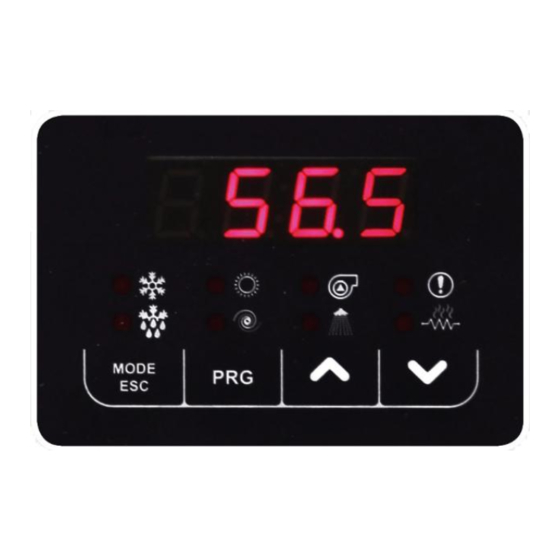
Page 9: User Interface - Controller
5 USER INTERFACE - CONTROLLER Select the operating mode and manually reset any alarms. Each time you press the key you have the following sequence: off cool heat off Mode If DHW is enabled, the sequence is the following: off ... -
Page 10: Setpoint Menu
5.2 SETPOINT MENU The various setpoints can be viewed and edited. SETPOINT DESCRIPTION UNIT DEFAULT RANGE First Summer setpoint °C 5 - Co2 First Winter setpoint °C 45.0 25 - 60 *San Sanitary setpoint °C 48.0 25 - 60 Coo2 Second Summer setpoint °C 18.0... -
Page 11: Alarms Menu [Err]
5.5 ALARMS MENU [Err] This menu is only displayed if there are triggered alarms. All of the active alarms can be seen. This is a multi- circuit machine. Therefore all the alarms are divided by circuit (label ALCx grants access to the alarms of circuit number x). -
Page 12: Firmware Update [Updf]
CAUTION All the operations with INSTALLER visibility must be carried out by QUALIFIED PERSONNEL. The company excludes any contractual and extra contractual liability for damage caused to persons, animals or objects, by incorrect installation, setting and maintenance, improper use of the equipment, and the partial or superficial reading of the information contained in this manual. -
Page 13: Led
5.12.1 LED ON if the compressor is running OFF if the compressor is off Compressor LED FLASHING if pending the timed compressor start ON if sanitary mode enabled OFF if sanitary mode disabled Domestic hot water LED ... -
Page 14: Editing Dynamic Set-Point
X12-1 X12-2 XGI-3.2 XGI-2.2 XGI-1.2 X-14.2 X-11.2 X-17.2 X-4.1 X-10.2 X-9.2 X-6.2 X-22.2 X-20.2 X-19.2 X-15.2 X-16.2 X-5.2 XGI-3.1 XGI-2.1 XGI-1.1 X-14.1 X-11.1 X-10.1 X-6.1 X-20.1 X-19.1 X-9.1 X-22.1 X-17.1 X-15.1 X-16.1 X-5.1 6 EDITING DYNAMIC SET-POINT The regulator allows you to modify the set-point by adding up the value according to the temperature of the outdoor air probe. -
Page 15: Edit The Set-Point From 0-10V Input
Setpoint Setpoint CURVE Heat Cool 20°C 18°C 20°C -27°C 20°C 13°C 20°C -25°C 20°C 25°C 20°C -29°C 40°C 10°C 20°C -28°C 40°C 15°C 20°C -25°C 5°C 5°C 37°C -17°C 10°C 8°C 40°C -20°C 6.2 EDIT THE SET-POINT FROM 0-10V INPUT Another type of adjustment allows you to edit the setpoint by adding (or subtracting) a value depending on the 0-10V input (if enabled). -
Page 16: Continuous Operation [P03=0] - Default
The circulator can be configured with P03 to operate independently from the compressor or on call. 0=continuous operation in heating/cooling mode(default P03=0) 1=operating on call by temperature controller Note: with automatic reset flow switch alarm triggered, the circulator is on even if the compressor is off. The circulator is always on when the antifreeze heaters are running and if operation of the hydraulic pump in antifreeze is enabled. -
Page 17: Operation With Heater Active
7.4 OPERATION WITH HEATER ACTIVE See paragraph 9.8. 7.5 PROPORTIONAL REGULATION OF THE CIRCULATOR The speed of the circulator changes depending on the temperature difference between the inlet water and outlet water of the heat exchanger, according to the diagram below, where: ... -
Page 18: Enabling Domestic Hot Water Production
The water antifreeze heaters on the faces of the evaporator plates even activate with the machine off (but powered) when the delivery water temperature drops below r02 °C (default 4°C) in “heating” mode or below r03 °C (default 4°C) in “cooling” mode or when switched “OFF”. The heaters are switched off when the temperature measured by the outlet water probe exceeds r02+r06 in “heating”... -
Page 19: Memorising The Probe In Heating Mode
9.2.1 MEMORISING THE PROBE IN HEATING MODE Switching from utility water to domestic hot water, the working probe changes from “water outlet probe” to “DHW tank probe”. For this reason, in heating mode, before entering sanitary mode, the last value read by the heat pump delivery probe is stored. -
Page 20: System Water Remote Probe
way activation of the domestic hot water function is controlled by the tank probe connected to the first unit, while the other units are enabled automatically by digital consent. The system goes to sanitary mode when the digital input closes and exits DHW production when it opens. I/O resource - Parameter Value Function Closed contact ... -
Page 21: Plant Heater
9.6.1 PLANT HEATER If the regulation temperature remains below water setpoint in heating (Hea) – 0.5°C for a time equal to r12 the integration heater is activated according to operation of the machine in joint time slots or in substitution, as indicated in Paragraph 9.11. The heater switches off when the setpoint is reached (also taking into account an offset set with parameters r29 or r30). -
Page 22: Integration Heater Selection Mode
9.7 INTEGRATION HEATER SELECTION MODE The priority can be set in the order to activate the plant side and sanitary side integration heaters; specifically the configurations are: 1. r14=0 (default), the heaters can be activated simultaneously, if present; 2. r14=1, the heaters can be activated, excluding one another: 2.1. -
Page 23: Activation Of Integration Heaters And Boiler In Joint Operation And In Substitution Of Heat Pump Compressor
9.10 ACTIVATION OF INTEGRATION HEATERS AND BOILER IN JOINT OPERATION AND IN SUBSTITUTION OF HEAT PUMP COMPRESSOR The auxiliary parts that can be used for joint operation or for operation in substitution are: - boiler - plant integration heater - DHW integration heater Considering the operating modes in heating and/or DHW, there are 4 operating areas: .[°C] . -
Page 24: Operation In Substitution
Note: In the joint operating bracket, the boiler is temperature controlled by the plant water remote probe (if enabled). In particular, if the temperature detected by the remote probe is lower than the Hea setpoint, the boiler is switched on and then will go off when the temperature detected by the remote probe is higher than the Hea setpoint. - Page 25 HEAT / BOTH IN HEAT 1) Boiler 0/1/2 HEAT+SAN AND IN DHW 1) Plant/DHW integration heater HEAT / BOTH IN HEAT 2) After r12 minutes, boiler HEAT+SAN AND IN DHW minutes minutes 1) Boiler HEAT / BOTH IN HEAT After minutes, plant/DHW HEAT+SAN...
- Page 26 TABLE 3. JOINT OPERATION, BRACKET 2 N° INTERVENTION ORDER STATUS OPERATION (with setpoint not reached) 1) Boiler HEAT / HEAT 0/1/2 1/3/4/6 2) After r12 minutes, heat pump HEAT+SAN minutes 1) Boiler 2) After r12 minutes, plant integration HEAT / HEAT 0/1/2 heater...
- Page 27 TABLE 4. OPERATION IN SUBSTITUTION INTERVENTION ORDER N° STATUS OPERATION (with setpoint not reached) 1) Boiler HEAT / 2) After r12 minutes, Plant HEAT 0/1/2 HEAT+SAN integration heater minutes 1) Plant integration heater HEAT / HEAT 0/1/2 2) After r12 minutes, boiler HEAT+SAN minutes 1) Boiler...
-
Page 28: Auxiliary Systems Offset Management
Table 6 shows the behaviour of the plant and DHW integration heaters in all the operating modes of the unit. TABLE 6. INTEGRATION HEATERS OPERATION N° STATUS OPERATION PLANT INTEGRATION HEATER DHW INTEGRATION HEATER In “HEAT+SAN”, by default sanitary temperature control has priority over that of the plant, therefore if required by the temperature control, HEAT+SAN... -
Page 29: Machine Block
9.12.3 MACHINE BLOCK A live output can be configured signalling the presence of an alarm. I/O resource - Parameter Value Function DO7 can be activated via Alarm warning 9.12.4 DEFROST A digital output can be configured signalling defrosting in progress. I/O resource –... -
Page 30: Functions That Can Be Activated With Hi-T2 Accessory (Optional)
I/O Ports - Paramete Value Function Enablement of the maximum Hz function Activation of Maximum Hz function in cooling mode. Activation of Maximum Hz function in heating mode. Activation of Maximum Hz function in DHW mode. Activation of Maximum Hz function in cooling and DHW mode. Activation of Maximum Hz function in heating and DHW mode. -
Page 31: Management Of Secondary Circulator/Booster Pump (With Room Thermostat)
XGI-8.1 XGI-9.1 XGI-7.1 XGI-5.1 XGI-4.1 XGI-3.1 XGI-2.1 ID 9E 4.1 / 4.2 Not Set Voltage-free digital input 5.1 (phase) 230Vac, 50Hz, 2A (AC1) single-phase live DO 1E Not Set 6.1(neutral) output. 5.2 (phase) 230Vac, 50Hz, 2A (AC1) single-phase live DO 2E Not Set 6.1(neutral) output. -
Page 32: Determination Of Setpoint
DO2E can be Live output Valve close command 5.1 (phase) activated via H87 Mixer management only active in heating mode Mixer management only active in cooling mode Mixer management only active in heating and cooling mode 11.3.1 Determination of setpoint The setpoint on which to perform regulation is given by rCO or rHE respectively in cooling and heating mode. -
Page 33: Activation Of Solar Circulator
11.4.1 Activation of solar circulator Solar management is also active with the unit off. The solar circulator is active in both of the following conditions are met: The temperature of the solar collector is higher than that defined by parameter S13 (default 40°C), the solar circulator is activated;... -
Page 34: Tables Of Permitted Setups For User And Installer
Note: Solar integration is NOT managed if the controller of the unit is OFF; The remote digital input OFF has no effect on solar management; During first ignition, check that the probe of the solar collector measures a temperature lower than 160°C and that this temperature corresponds to that read on the controller of the internal unit Solar circulator live output 230V ac, 50Hz, 2A (AC1). - Page 35 Allowed configurations Notes Parameter Description Unit Default Range Visibility Description First cooling setpoint °C 25-Coo2 First heating setpoint °C 45.0 Hea2-H01 Sanitary setpoint °C 48.0 25-H01 If sanitary function active. See par. 9.2 Coo2 Second cooling setpoint °C 18.0 Coo-25 Hea2 Second heating setpoint °C...
- Page 36 2 = ID8E1 polarity inverted 4 = ID9E1 polarity inverted 8 = ID10E1 polarity inverted 16 = ID1E2 polarity inverted 32 = ID2E2 polarity inverted 64 = ID3E2 polarity inverted 128 = ID4E2 polarity inverted 0 = Output disabled Output configuration 0-47 22 = Plant integration heater In DO3 power...
- Page 37 Pump OFF compressor OFF delay 0-25.5 Pump operating mode See par.7 The pump is always on if the antifreeze heaters are active. Pump setting in antifreeze °C -15-15 See par.7 Pump hysteresis in antifreeze °C 0.0-15.0 See par.7 Modulating pump inlet/outlet water delta T setting °C 0-15 See par.7...
-
Page 38: Alarms
13 ALARMS By placing the controller in OFF mode, the alarms reset and the counts of the relative hour interventions are also reset. If the alarms are still triggered when switching the unit back on, contact technical assistance. The values indicated below could be subject to updates. If you have any doubts, contact our headquarters. 13.1 [E006] FLOW SWITCH The water side flow switch is already installed inside the unit and MUST NOT be tampered with or bypassed in any way. -
Page 39: E008] Driver Limitation
In heat pump mode, if the pressure transducer on the unit detects a pressure lower than 1.3 bar, the alarm is triggered. The alarm is reset when the pressure rises 2.0 bar above the triggering threshold. A bypass time of 60 seconds is counted every time the compressor is activated. When the alarm is triggered, it blocks the compressors of the circuit. -
Page 40: Utilities Block Alarm Table
13.2 UTILITIES BLOCK ALARM TABLE Code Description Block E000 Remote off Machine E001 High pressure alarm Machine E002 Low pressure alarm Machine E005 Antifreeze alarm Machine E006 Flow alarm Machine E008 Compressor driver limitation alarm Machine E009 Discharge high temperature alarm Machine E010 Solar collector high temperature alarm... - Page 41 To configure the Modbus communication according to your requirements, you must modify the following logs: H124 : BAUD RATE 4800 9600 19200 38400 H125 : PARITY, STOP BIT NONE, 2 bit ODD, 1 bit EVEN, 1 bit NONE, 1 bit H126 : DEVICE ID 1 - 200 Format...
- Page 42 °C/10 Compressor 1 discharge °C/10 Plant remote If active 7000 %/10 Condensing fan Analogue outputs 7001 %/10 Circulator pump ALARM - E01 * High pressure ALARM - E02 * Low pressure ALARM - E03 * compressor 1 circuit breaker ALARM - E04 * fan1 circuit breaker ALARM - E05 Reset alarms: with...
- Page 43 ALARM - E971 EEPROM inverter 1 ALARM - E972 *EEPROM inverter 2 (*) if any...
- Page 44 Fonderie Sime S.p.A - Via Garbo, 27 - 37045 Legnago (Vr) Tel. +39 0442 631111 - Fax +39 0442 631292 - www.sime.it...
Need help?
Do you have a question about the SHP M Eco Series and is the answer not in the manual?
Questions and answers