
Related Manuals for Planer 370-M Series

Summary of Contents for Planer 370-M Series
- Page 1 ® Series 370-M & 570-M Instructions for use © 2023 Planer Limited Original instructions MA201231-M-EN 1.0.1...
-
Page 3: Table Of Contents
Operating the equipment Installation ........................20 2.1.1 Installing the liquid nitrogen supply ..............20 Using a Planer pump and dewar ................21 Configuring the controller ..................21 Freezing samples ......................21 2.4.1 Loading the samples in the lid assembly ............... 21 2.4.2... - Page 4 Table of Contents 3.3.3 The chamber will not cool ..................30 3.3.4 The chamber will not heat ..................30 3.3.5 No response from the system ................31 3.3.6 Returning for service ....................31 Disposal ......................... 31 Additional information Specifications ....................... 34 4.1.1 System specifications .....................
-
Page 5: Introduction
Introduction... -
Page 6: Notices
TW16 7HD, UK. Tel: +44 (0)1932 755000; email: sales@planer.com Serious incidents that occur with this device should be reported to Planer Ltd and the competent authority of the Member State in which the user and/or patient is established. This equipment contains batteries and other components that have a limited life. To ensure the long life of the equipment and help ensure trouble-free operation, we recommend that you join one of our Maintenance and Support Schemes. -
Page 7: Symbols
Introduction Symbols 1.2.1 Symbols used in this manual Warning. Information or instructions that are related to safety. Failure to follow these instructions may result in personal or third-party injury. Caution. Important information or instructions related to the safe use of the equipment. -
Page 8: Safety Precautions
Introduction Fuse 1 Fuse 2 Fuse 3 Fuse 4 MAINS INLET Mains power inlet (Kryo 370) Liquid nitrogen inlet (Kryo 570) LN2 INPUT Liquid nitrogen inlet (Kryo 370) REMOTE PRT Sample temperature probe input (Kryo 570) SAMPLE PRT Sample temperature probe input (Kryo 370) Do not dispose of with general waste. -
Page 9: First Aid
Introduction 1.3.1 First aid IF IN DOUBT, SEEK IMMEDIATE MEDICAL ATTENTION. If any quantity of liquid nitrogen comes into contact with the skin or eyes, immediately flush that area of skin with large quantities of tepid water. Do not use strong flows of water as this could cause tissue damage. Continue to flush the area and seek medical attention. -
Page 10: Liquid Nitrogen And Vessels
Introduction Cautions The connectors on the equipment must only be used for connection to other equipment described in this document. When heating under manual control, check the chamber temperature at intervals of 30 seconds or less to avoid overheating. User servicing is limited to cleaning and decontamination. All other servicing must only be undertaken by suitably trained engineers. -
Page 11: Emc Precautions
Introduction Stand clear of boiling and splashing liquid nitrogen and its gas when filling a dewar or when inserting objects, such as a pump, into the liquid. Use tongs or wear suitable protective gloves when handling cold or hot objects. Never remove a pump from a dewar until the pressure gauge reading has fallen to zero. -
Page 12: Equipment Overview
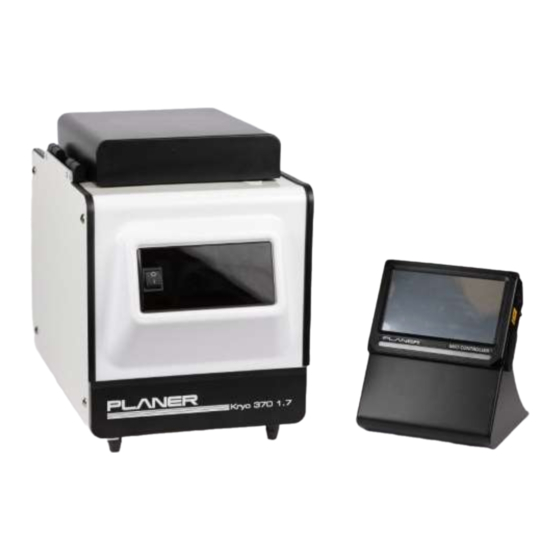
Introduction 1. Controller: measures the current temperature and adjusts the amount of liquid nitrogen or heat that is supplied to the chamber. 2. Chamber: contains the samples being cooled and houses the heater and liquid nitrogen injection components. The chamber temperature is controlled by injecting liquid nitrogen into the chamber and by switching on an internal heater. -
Page 13: Mr7 Controller
Introduction 1.6.3 MR7 controller 1.6.3.1 Guide to the MR7 controller The equipment is designed to cool samples by following a predefined time-temperature profile. The temperature-time relationship is referred to as the profile. The equipment comprises two main elements: 1. <%MR7_CONTROLLER%>: the user interface and temperature controller. This comprises two internal subsystems: IO Control Board: measures the current temperature and adjusts the amount of... -
Page 14: Connection Overview
Introduction 1.6.4 Connection overview 1.6.4.1 Chamber All connectors are located at the back of the freezer. Fig.6 Connections on the back of the 300 series freezer Liquid nitrogen inlet INPUT SAMPLE Sample temperature probe input LNP4 Power outlet for LNP4 pump only ONLY MAINS Mains power inlet... - Page 15 Introduction Fig.7 Connections on the back of the 500 series freezer Liquid nitrogen inlet REMOTE Sample temperature probe input Power outlet for MRV and LNP4 pump only POWER MAINS Mains power inlet INLET Series 370-M & 570-M: Instructions for use MA201231-M-EN 1.0.1...
-
Page 16: Mr7 Controller
Introduction 1.6.4.2 MR7 controller All connectors are at the bottom of the MR7 system control box. Fig.3 Connections on the MR7 control box DC power input Controller rate freezer connector. Primary temperature probe input Secondary temperature probe input Serial port. For use by trained service personnel only. Alarm output USB connection. - Page 17 Introduction Fig.4 Connections for the 300 series freezers Fig.5 Connections for the 500 series freezers Series 370-M & 570-M: Instructions for use MA201231-M-EN 1.0.1...
- Page 19 Operating the equipment...
-
Page 20: Operating The Equipment Installation
Installing the liquid nitrogen supply Warning Installation must only be undertaken by suitably trained personnel. Your service provider will connect the chamber to a liquid nitrogen cylinder or a Planer pump and dewar. Series 370-M & 570-M: Instructions for use MA201231-M-EN 1.0.1... -
Page 21: Using A Planer Pump And Dewar
Operating the equipment Using a Planer pump and dewar For instructions on how to use the Planer LNP4 pump and dewar see MA007422, LNP4- FS instructions for use. Configuring the controller For details of how to configure the MR7 controller see MA200524, MR7 Instructions for use. -
Page 22: Preparing The Nitrogen Supply
2.4.2 Preparing the nitrogen supply Caution Ensure that you have enough liquid nitrogen to complete your freezing run. If using a Planer pump and dewar, follow the instructions in Using a Planer pump and dewar If using a cylinder, refer to the manufacturer's instructions on how to switch on the supply. -
Page 23: Loading The Samples Using An Mr7
Operating the equipment Fig.1 Log in screen 3. Select how you want to run the profile: a. If you intend to run the profile using DeltaT, select Control from PC and then refer to the DeltaT documentation. b. If running directly from the controller, select profile. -
Page 24: Removing The Samples
Operating the equipment 2. After loading the samples, wait five minutes to allow the chamber to re-stabilise. 3. Then press on the controller to start the run. 4. The profile will now run. 5. At the end of the run, the controller will prompt you when the samples are ready for removal. -
Page 25: Switching Off The System
Operating the equipment Switching off the system CAUTION Switching off the chamber at sub-zero temperatures may cause serious damage to the equipment. If connected to a liquid nitrogen cylinder, allow the hose to thaw and warm up to room temperature before shutting off the valve on the cylinder. 1. - Page 27 Routine maintenance and troubleshooting...
-
Page 28: Routine Maintenance And Troubleshooting Routine Maintenance
Routine maintenance and troubleshooting Routine maintenance and troubleshooting Routine maintenance Warning Before cleaning: o Switch off the equipment. o Disconnect the mains supply at the wall socket. o Turn off any connected liquid nitrogen cylinders. o Open the red pressure relief valve on the pump. Wait until the pressure on the gauge has fallen to zero and the flow of gas has stopped. -
Page 29: Calibrating The System
Routine maintenance and troubleshooting Warning The equipment is classified as Class I equipment and must be earthed for safe operation. Repetition of potentially damaging high-voltage flash tests should be avoided. To ensure adequate earth bonding, the equipment and mains cables must be regularly checked by suitably trained personnel using a Portable Appliance Tester or similar equipment. -
Page 30: The Chamber Will Not Cool
Check the nitrogen supply. Check the fuses. If using a Planer pump, check that the pump filter is not blocked by ice. 3.3.4 The chamber will not heat Warning Refer to the safety instructions at the front of this manual. -
Page 31: No Response From The System
3.3.6 Returning for service Should the equipment or any part of the equipment need to be sent back to Planer Limited for repair, or if the equipment is to be inspected, maintained or repaired on-site by Planer Limited personnel, a Decontamination Certificate must be completed. This can be downloaded from http://www.planer.com/support/service/decontamination-... -
Page 33: Additional Information
Additional information... -
Page 34: System Specifications
Additional information Additional information Specifications 4.1.1 System specifications Accuracy ±(0.3 + 0.005 x TM) °C (where TM is the magnitude of the temperature). Storage temperature -10 °C to +50 °C Storage humidity 5% to 95% relative humidity non-condensing Operating environment For indoor use only Operating temperature +5 °C to +40 °C... -
Page 35: Chamber Specifications
Additional information 4.1.3 Chamber specifications Kryo chamber 370-1.7 570-16 570-ART Weight kg Capacity litres Dimensions mm 420 x 300 x 520 515 x 670 x 500 515 x 670 x 500 (External H x W x Dimensions mm 200 x Ø150 350 x 230 x 230 350 x 230 x 230 chamber access... -
Page 36: Fuses
Kryo 370-1.7 F1 and F2 115V ~ model T 10A H 250V T 5A L 250V (Planer # FL013299) (Planer #FL013801) 230 V~ model T 5A L 250V T 2.5A L 250V (Planer #FL013801) -
Page 37: Index
INDEX - A - - M - alarm maintenance external routine medical attention - C - - P - calibrating chamber precautions connectors specification profile starting connectors chamber pump controller using controller - R - calibrating connectors specifications removing samples - D - reports reset... - Page 38 INDEX system no response specification - T - theory of operation troubleshooting no response run stopped will not cool will not heat - U - unexpected reset Series 370-M & 570-M: Instructions for use MA201231-M-EN 1.0.1...
- Page 39 Planer Limited, 110 Windmill Rd., Sunbury-on-Thames, Middlesex, TW16 7HD, UK. www.planer.com Tel: +44 (0)1932 755000 Series 370-M & 570-M: Instructions for use MA201231-M-EN 1.0.1...
Need help?
Do you have a question about the 370-M Series and is the answer not in the manual?
Questions and answers