
Related Manuals for Stulz EC Tower ECD 91


Summary of Contents for Stulz EC Tower ECD 91
- Page 1 EC Tower ECD/U 091, 181, 251 (Version 07) Technical manual Precision Air Conditioning Units Index G22 400V/50Hz/3Ph/N/PE Issue 1.2019...
- Page 2 EC TO W E R T EC H N I CA L M A N UA L A B O U T S T U L Z Since it was founded in 1947, the STULZ company has evolved into one of the world’s leading system suppliers of air-conditioning technology.
- Page 3 For inquiries and service, please contact your local STULZ partner. At www.stulz.com you will find a partner near you as well as the entire global STULZ sales network. © STULZ GmbH – all rights reserved EN/01.2019/G22...
-
Page 4: Table Of Contents
7.6 Establishing the conductivity of the feed water ................... 47 7.7 Connecting the steam humidifier to the feed water................48 7.7.1 On-site preparations........................... 48 7.7.2 Connecting the Downflow unit to the feed water ..............48 Subject to technical modifications. EN/01.2019/G22 © STULZ GmbH – all rights reserved... - Page 5 13.6.2 Installing the duct connection ....................... 95 13.7 Installing the flexible canvas fitting ....................... 96 13.8 Installing the louver damper for Upflow units..................98 13.8.1 Installing the louver damper ......................99 13.8.2 Electrically connecting the louver damper ................99 © STULZ GmbH – all rights reserved EN/01.2019/G22...
- Page 6 14.5 Data sheet for temperature and humidity sensor B03 for supply air ........196 14.6 Installation instructions for louver damper servo motor .............. 200 15. CE Declaration of Conformity for the EC Tower ............. 204 EN/01.2019/G22 © STULZ GmbH – all rights reserved...
-
Page 7: Information On This Document
This air conditioning unit uses refrigerant R410A. Refrigerants are hydrofluorocarbons (HFCs) that are either volatile or are liquefied under pressure and highly volatile. They are non-combus- tible and, if handled correctly, are not hazardous to health. © STULZ GmbH – all rights reserved EN/01.2019/G22... -
Page 8: Handling Refrigerants
A unit protocol must be kept. b. To be stored in the proximity of the unit c. Access for competent staff in case of repairs and repeated inspection must be ensured. EN/01.2019/G22 © STULZ GmbH – all rights reserved... -
Page 9: Other Applicable Documents
• Technical Manual for outdoor unit • Circuit diagram (supplied with the air conditioning unit on delivery • Start-up report for EC Tower (for ECD/U 091, 181, 251 (version 07)) • Technical Manual for WIB 8000 © STULZ GmbH – all rights reserved EN/01.2019/G22... -
Page 10: Residual Risks
Do not stand over the blower outlet. Junction boxes 1 Short-circuit Flashover, caustic fumes Tighten clamped connections, and 2 wear protective gloves. EN/01.2019/G22 © STULZ GmbH – all rights reserved... - Page 11 Junction boxes 1 Voltage on electrical sup- Electric shock Check that supply cable is free and 2 ply cable from voltage before removing, wear protective gloves. © STULZ GmbH – all rights reserved EN/01.2019/G22...
-
Page 12: Transport / Storage
EC TO W E R T EC H N I CA L M A N UA L 4. Transport / Storage 4.1 Delivery of units Stulz A/C units are mounted on pallets and packed several times in plastic film. NOTE The refrigerant circuit is filled with inert gas. -
Page 13: Storage
• the storage point must not be exposed to direct sunlight. Observe the storage conditions in the chapter “Application limits“. • store the unit packaged to avoid the risk of corrosion. © STULZ GmbH – all rights reserved EN/01.2019/G22... -
Page 14: Description
D = Downflow U = Upflow EC = EC Tower Page code EN/01.2019/G22 Date of issue Index number month/year Language: Manufacturing base: EN = English G = Germany C = China I = Italy EN/01.2019/G22 © STULZ GmbH – all rights reserved... -
Page 15: Proper Use
The EC Tower is designed for removing high heat loads from 150 to 700 W/m² from small and medium-sized equipment rooms. Any other use beyond the above is regarded as improper use. Stulz cannot be held liable for damage resulting from such use. The plant operator is the sole bearer of this risk. -
Page 16: Ec Tower Method Of Operation
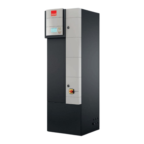
ECD 91 - Front Temp./humidity sensor B01 Junction box 1 Air filter Electric heater Steam cylinder (detailed view) Steam nozzle Steam cylinder Stop valves Junction box 2: For communication with the outdoor unit EN/01.2019/G22 © STULZ GmbH – all rights reserved... - Page 17 ECD 181/251 - Front Temp./humidity sensor B01 Air filter Junction box 1 Electric heater Steam cylinder (detailed view) Steam nozzle Steam cylinder Stop valves Junction box 2: For communication with the outdoor unit © STULZ GmbH – all rights reserved EN/01.2019/G22...
- Page 18 ECU 181/251 - Rear Junction box 1 Electric heater Steam humidifier (detailed view) Steam lance Hose Steam cylinder Junction box 2 Junction box 2: Temp./humidity sensor B01 For communication with the Stop valve outdoor unit EN/01.2019/G22 © STULZ GmbH – all rights reserved...
- Page 19 Gas line Overheating protection No switching or techni- THI-A Interior of EC Tower cal function Return air duct of EC Temperature/humidity Tower sensor THI-R2 THI-R1 THI-R3 Heat exchanger Gas line THI-A Injection line © STULZ GmbH – all rights reserved EN/01.2019/G22...
-
Page 20: Ec Tower Sizes And Versions
In Downflow units, the warm air is sucked into the top of the indoor unit. The cold air is blown out downward into the raised floor or into the blow-out plinth. Upflow ECU 91, 181, 251 Downflow ECD 91, 181, 251 EN/01.2019/G22 © STULZ GmbH – all rights reserved... -
Page 21: Heater Method Of Operation
“C7000 controller for EC Tower”). The heater is available for sizes 1 and 2. Start-up and operation The heater is controlled and monitored via the controller. No further measures are required for start-up or operation. © STULZ GmbH – all rights reserved EN/01.2019/G22... -
Page 22: Technical Data
FDC 140 VSX FDC 200 VSA FDC 250 VSA ZSX-S Minimum heat load of room requi- 4. 3 ring cooling Minimum airflow rate for cooling/ m³/h 1,000 1,200 3,200 3,200 3,200 3,200 humidification/dehumidification EN/01.2019/G22 © STULZ GmbH – all rights reserved... - Page 23 This results in a pressure drop in the upper and lower ranges. This drop in low pressure causes the temperature of the heat exchanger in the indoor unit to fall, activating the frost protection control in this heat exchanger at short intervals. This makes cooling mode impossible. © STULZ GmbH – all rights reserved EN/01.2019/G22...
-
Page 24: Ec Tower Technical Data
The remainder contributes to (unwanted) dehumidifica- tion of the air. For use in equipment rooms, the SHR should be higher than 0.9 at +24 °C and 50 %. EN/01.2019/G22 © STULZ GmbH – all rights reserved... - Page 25 59.4/57.2 62.5/60.2 (Version 07) 1,861 x Dimensions (HxWxD) 1,861 x 600 x 701 1,861 x 1,000 x 911 1,000 x 911 Footprint (WxD) 600 x 600 1,000 x 810 1,000 x 810 Weight © STULZ GmbH – all rights reserved EN/01.2019/G22...
- Page 26 Ø 16/ Ø 16/ Ø 16/ Ø 22/ Ø 1/2" Ø 5/8" Ø 5/8" Ø 5/8" Ø 7/8" unit connection inches Ø 7/8" Thermal insulation, imperme- All pipes able to vapor diffusion EN/01.2019/G22 © STULZ GmbH – all rights reserved...
-
Page 27: Electrical Data And Circuit Diagram Of Ec Tower
Pay attention to the EC Tower operating and connection data („6.5 Operating and connection data of EC Tower“ on page 29). The circuit diagram varies depending on the unit size and version. The correct circuit diagram is enclosed with the unit on delivery. © STULZ GmbH – all rights reserved EN/01.2019/G22... -
Page 28: Dimensional Drawings
EC TO W E R T EC H N I CA L M A N UA L 6.4 Dimensional drawings All dimensions in mm. Size 1 ECU/D 91 Size 2 ECU/D 181 ECU/D 251 1000 EN/01.2019/G22 © STULZ GmbH – all rights reserved... -
Page 29: Operating And Connection Data Of Ec Tower
EC TO W E R T EC H N I CA L M A N UA L 6.5 Operating and connection data of EC Tower 6.5.1 ECU/D 091 size 1 - Version 07 © STULZ GmbH – all rights reserved EN/01.2019/G22... - Page 30 EC TO W E R T EC H N I CA L M A N UA L EN/01.2019/G22 © STULZ GmbH – all rights reserved...
-
Page 31: Ecu/D 181 Size 2 - Version 07
EC TO W E R T EC H N I CA L M A N UA L 6.5.2 ECU/D 181 size 2 - Version 07 © STULZ GmbH – all rights reserved EN/01.2019/G22... - Page 32 EC TO W E R T EC H N I CA L M A N UA L EN/01.2019/G22 © STULZ GmbH – all rights reserved...
-
Page 33: Ecu/D 251 Size 2 - Version 07
EC TO W E R T EC H N I CA L M A N UA L 6.5.3 ECU/D 251 size 2 - Version 07 © STULZ GmbH – all rights reserved EN/01.2019/G22... - Page 34 EC TO W E R T EC H N I CA L M A N UA L EN/01.2019/G22 © STULZ GmbH – all rights reserved...
-
Page 35: Installing The Ec Tower
EC Tower without air blow-out plenum: EC Tower with air blow-out plenum: Air intake zone in Downflow units and air No duct connection for air blow-out blow-out zone in Upflow units without zone in Upflow units duct connection © STULZ GmbH – all rights reserved EN/01.2019/G22... -
Page 36: Opening The Ec Tower
9. Access to junction box 2: Remove the four Door of junction box 1 screws in the sheet metal cladding of junction box 2. Central front panel Lower front panel Master switch Junction box 2 EN/01.2019/G22 © STULZ GmbH – all rights reserved... - Page 37 10. Remove the lower front panel. The front panel is secured with ball studs and can be removed Master switch without tools. 11. Access to junction box 2: Remove the four screws in the sheet metal cladding of junction box 2. © STULZ GmbH – all rights reserved EN/01.2019/G22...
-
Page 38: Connecting The Pipes
The locations of the pipe connections have a tolerance of ± 10 mm. 43 mm 121 mm View A: The locations of the pipe connections have a tolerance All dimensions in mm. of ± 10 mm. EN/01.2019/G22 © STULZ GmbH – all rights reserved... - Page 39 The locations of the pipe connections have Indoor unit a tolerance of ± 10 mm. Suction line Sz Injection line Ez View A: View from rear: All dimensions in mm. 411 mm Injection line Suction line © STULZ GmbH – all rights reserved EN/01.2019/G22...
- Page 40 Suction line Injection line The locations of the pipe connections have a toleran- ce of ± 10 mm. Injection line Suction line View from below: View A: 55 70 All dimensions in mm. EN/01.2019/G22 © STULZ GmbH – all rights reserved...
- Page 41 View from rear: Connection dimensions Indoor unit Suction line Injection line The locations of the pipe connections have a toleran- ce of ± 10 mm. View B: View A: 55 70 All dimensions in mm. © STULZ GmbH – all rights reserved EN/01.2019/G22...
-
Page 42: Installing The Drain
The hot water condensate pump is an optional accessory of the EC Tower, see section “13. Options“ on page 75. The pressure pipe must have an inside diameter of 9 mm. The pressure pipe is not EN/01.2019/G22 © STULZ GmbH – all rights reserved... - Page 43 The diagram below shows the drainage pipe installation with hole in the right-hand side panel. Components colored gray are not included with the EC Tower, and must be provided by the customer. © STULZ GmbH – all rights reserved EN/01.2019/G22...
- Page 44 3. Use a drain hopper when fitting the end of the drainage pipe. The drain hopper is not included with the EC Tower, and must be provided by the customer. End of drainage pipe Drain hopper EN/01.2019/G22 © STULZ GmbH – all rights reserved...
- Page 45 Condensate cannot drain freely: End of drainage pipe in the water EC Tower Trapped air in drainage pipe generates noise Do not bend or kink drai- nage pipe Wall drain © STULZ GmbH – all rights reserved EN/01.2019/G22...
-
Page 46: Installing The Refrigerant Circuit
EC TO W E R T EC H N I CA L M A N UA L 7.5 Installing the refrigerant circuit Refrigerant circuit installation is described in the outdoor unit Instruction Manual. Install the refrigerant circuit as shown in the RI flow diagram below: EN/01.2019/G22 © STULZ GmbH – all rights reserved... -
Page 47: Establishing The Conductivity Of The Feed Water
- If the figure provided by the water supplier matches the medium conductivity of the steam cylinder, you can use the installed steam cylinder. - If the figure provided by the water supplier does not match the medium conductivity of the steam cylin- der, replace the installed steam cylinder. © STULZ GmbH – all rights reserved EN/01.2019/G22... -
Page 48: Connecting The Steam Humidifier To The Feed Water
Remove the central front panel. Remove the lower front panel. The front panel is secured with ball studs and can be removed without tools. Remove the left and right-hand cover panels next to junction box 2. EN/01.2019/G22 © STULZ GmbH – all rights reserved... - Page 49 Fit the left and right-hand cover panels. 10. Fit the lower front panel. 11. Fit the central front panel. 12. Close the door of junction box 1 using the supplied triangular socket wrench. © STULZ GmbH – all rights reserved EN/01.2019/G22...
-
Page 50: Connecting The Upflow Unit To The Feed Water
Pull the plastic hoses out of the central front panel. Remove the central front panel. Remove the lower front panel. The front panel is secured with ball studs and can be removed without tools. EN/01.2019/G22 © STULZ GmbH – all rights reserved... - Page 51 13. Position the central front panel on the EC Tower. 14. Fit the plastic hoses to the central front panel. 15. Fit the central front panel. 16. Close the door of junction box 1 using the supplied triangular socket wrench. © STULZ GmbH – all rights reserved EN/01.2019/G22...
-
Page 52: Electrically Connecting The Ec Tower
• Make sure that phase imbalance does not exceed 2 %. • Phase imbalance can be determined by measuring the voltages between the outer conductors. • Do not exceed the mean value of the voltage differences of 8 V. EN/01.2019/G22 © STULZ GmbH – all rights reserved... -
Page 53: Circuit Diagram
Danger of death and of serious material damages due to wiring errors! • Avoid the following typical wiring errors. EC Tower EC Tower Example of EC Tower Example of INCORRECT INCORRECT installation! installation! © STULZ GmbH – all rights reserved EN/01.2019/G22... -
Page 54: Electrically Connecting The Ec Tower To Junction Box 1
Phase 1 (T1, T2, T3) on master switch (Q01) N wire on master switch (Q01) PE conductor to PE rail (X0) 4. Secure the cables with the strain relief screw. 5. Close the door of junction box 1. EN/01.2019/G22 © STULZ GmbH – all rights reserved... -
Page 55: Connecting The Outdoor Unit To The Ec Tower
Circuit-breaker F41 Terminal strip X1 Terminal strip X1 Master switch Q01 Master switch Q01 Terminal strip X0 Terminal strip X0 EC Tower EC Tower Door of junction box 1 Door of junction box 1 © STULZ GmbH – all rights reserved EN/01.2019/G22... -
Page 56: Connecting The Outdoor Unit Signal Lines In Junction Box 2
1. Connect the signal line of the outdoor unit to terminals (X1/1,2,3) in junction box 2 as per the circuit diagram. 2. Connect the PE conductor to terminal (X1/PE) in junction box 2 as per the circuit diagram. EN/01.2019/G22 © STULZ GmbH – all rights reserved... -
Page 57: Setting The Dip Switches Of The Printed Circuit Boards In Junction Box 2
• MHI outdoor unit: MHI outdoor unit board Components in junction box 2 02.02.2017 Junction box 2 Interface III k board MHI indoor unit board EC TOWER 091 D (VERSION 6) PAGE 1 / 1 Transformer © STULZ GmbH – all rights reserved EN/01.2019/G22... - Page 58 FDC 200 VSA FDC 250 VSA NOTE On series FDC71 to FDC250 outdoor air conditioning units, set DIP switch SW4-3 on the out- door air conditioning units to ON. EN/01.2019/G22 © STULZ GmbH – all rights reserved...
-
Page 59: Starting Up The Ec Tower
-X10 -F20 Control fuses Hutschiene mit Schrauben M5x25 befestigt. Circuit-breaker -Q70 140M-C2E-C20 Control fuse C09 - C23 Socket 230V Master switch -Q31 -Q71 -Q72 C09 - C23 C09 - C23 C09 - C23 © STULZ GmbH – all rights reserved EN/01.2019/G22... - Page 60 Table: Sizes and steam output of the EC Tower OEM model/steam output [kg/h] EC Tower KUET 1 / 1.5/3 KUET 2 / 5/8 Size 1 ● (ECD/U 91) Size 2 ● (ECD/U 181 and 251) EN/01.2019/G22 © STULZ GmbH – all rights reserved...
- Page 61 - Make sure that there is the correct number of windings as per the table above. Diagram: External current transformer (TAM) with windings 1 winding 2 windings 11. Determine the conductivity of the feed water (see section “7.6 Establishing the conductivity of the feed water“ on page 47). © STULZ GmbH – all rights reserved EN/01.2019/G22...
- Page 62 Setting [A] breaker Circuit-breaker 14.5 – Electrical supply to MHI Fuse F41: 16A-D 10.0 10.0 12.0 16.0 outdoor unit Steam humidifier – 11.2 Electric heater stage 1 – Electric heater stage 2 – EN/01.2019/G22 © STULZ GmbH – all rights reserved...
-
Page 63: Ec Tower Maintenance
Risk of injury from loose parts flying out from the rotating fan! • Inspect the fan for loose parts and tools after performing maintenance. • Remove loose parts and tools from the fan before switching on the air conditioning unit. © STULZ GmbH – all rights reserved EN/01.2019/G22... -
Page 64: Maintenance Intervals
• Do not use aggressive cleaning agents or solvents to clean the heat exchanger. • Clean the heat exchanger with compressed air. Blow along the fins against the normal airflow direction. • Alternatively, use a vacuum or steam cleaner. EN/01.2019/G22 © STULZ GmbH – all rights reserved... -
Page 65: Replacing The Filter Of Upflow Units
ECU 251 - Front view ECU 251 - Filter Description Description C7000AT controller Plastic hose Central front panel with filter Filter holder Door of junction box 1 Central front panel Master switch Filter © STULZ GmbH – all rights reserved EN/01.2019/G22... -
Page 66: Replacing The Filter Of Downflow Units
Incorrect removal of a soiled filter can cause contamination of the heat exchanger! • Exercise care when removing a soiled filter from the EC Tower. • Take care to ensure that no dirt gets onto the heat exchanger when removing the filter. EN/01.2019/G22 © STULZ GmbH – all rights reserved... - Page 67 4. Secure the EC Tower so it cannot inadvertently be switched on. 5. Affix a “DO NOT SWITCH ON” warning sign to the EC Tower. 6. Pull the long and short plastic hoses out of the filter. © STULZ GmbH – all rights reserved EN/01.2019/G22...
- Page 68 12. Fasten the short plastic hose to the filter. - Make sure that the short plastic hose is secured to the side of the filter with the cross brace facing the heat exchanger. EN/01.2019/G22 © STULZ GmbH – all rights reserved...
-
Page 69: Replacing The Filter In The Filtration Box In Downflow Units
8. Pull the filter out of the filtration box. 9. Push the new filter into the filtration box. - Make sure that the side of the filter with the cross brace is facing upward. 10. Close the service flap. © STULZ GmbH – all rights reserved EN/01.2019/G22... -
Page 70: Unit In General
2. Using a screwdriver, lift the coil out of the armature. 3. Clean the armature. 4. Position the new coil on the armature. Slide the coil into the armature until it audibly clicks into place. EN/01.2019/G22 © STULZ GmbH – all rights reserved... -
Page 71: Troubleshooting
(see Steam humidifier OEM User Manual, page 181 ff.). Further alarms may occur, depending on the options configured in the controller. # stands for a number when there are several components of the same type. © STULZ GmbH – all rights reserved EN/01.2019/G22... -
Page 72: Troubleshooting The Heater
Solenoid valve is Dirt between valve aperture and Dirt between valve aperture Clean valve body and membrane. leaking. membrane. and membrane. EN/01.2019/G22 © STULZ GmbH – all rights reserved... -
Page 73: Dismantling And Disposing Of The Ec Tower
9. Dispose of the EC Tower in accordance with local disposal and safety regulations. We recommend using a specialist recycling firm. The EC Tower contains the raw materials aluminum (heat exchanger), copper (pipes, cables) and iron (paneling). © STULZ GmbH – all rights reserved EN/01.2019/G22... -
Page 74: Spare Parts
ECU 91 only 1200274 Front door for ECU see „13.18“ Self-contained front door for on page on-site changeover of the air intake from the bottom or rear ○ ECU 181/251 only 1200275 EN/01.2019/G22 © STULZ GmbH – all rights reserved... -
Page 75: Options
Consists of a hot-dipped galva- nized sectional steel frame. With vibration-damping base. ECD 181/251 only 1200131 ● Technical data subject to change without notice; errors and omissions excepted. ○ NO © STULZ GmbH – all rights reserved EN/01.2019/G22... - Page 76 „13.14“ on ● ● 1200143 Four sensors maximum can be page 121 connected. ● Technical data subject to change without notice; errors and omissions excepted. ○ NO EN/01.2019/G22 © STULZ GmbH – all rights reserved...
- Page 77 WIB 8000 in separate box see „13.16“ on ● ● for operation via internet 1200148 page 127 browser. ● Technical data subject to change without notice; errors and omissions excepted. ○ NO © STULZ GmbH – all rights reserved EN/01.2019/G22...
-
Page 78: Installing The Condensate Pump
• Make sure that the condensate pipe, drainage pipe, pressure pipe and condensate pump fas- tening elements have a minimum temperature resistance of +99 °C. • Only use only a condensate pump for hot water (see “13. Options“ on page 75). EN/01.2019/G22 © STULZ GmbH – all rights reserved... -
Page 79: Checking The Product Package
Lower front panel Reset button on display of C7000AT Junction box 1 of EC Tower Central protective grill CPY controller of humidifier in junction box 1 Door on junction box 1 of EC Tower © STULZ GmbH – all rights reserved EN/01.2019/G22... - Page 80 11. Remove the right-hand cover panel. 12. Position the condensate pump next to the holes for the connections. Make sure that the condensate pump is horizontal. 13. Secure the condensate pump so it cannot tip over. EN/01.2019/G22 © STULZ GmbH – all rights reserved...
- Page 81 18. Connect the pressure pipe of the condensate pump to the pressure fitting. - Make sure that the pressure pipe has an inside diameter of 9 mm. 19. Fasten the pressure pipe to the pressure fitting using a cable tie. © STULZ GmbH – all rights reserved EN/01.2019/G22...
-
Page 82: Electrically Connecting The Condensate Pump To Ec Tower Size 1
-Q72 C09 - C23 C09 - C23 C09 - C23 -Q01 SAFETY FLOAT SWITCH 1102030 -K41 PUMP 180mm MOTOR NORMAL FLOAT SWITCH P U M P C A S I N G EN/01.2019/G22 © STULZ GmbH – all rights reserved... - Page 83 3. Connect fault signaling contact 1 of condensate pump to terminal (X4/3) in junction box 2. 4. Connect fault signaling contact 2 of the condensate pump to terminal (X4/4) in junction box 2. © STULZ GmbH – all rights reserved EN/01.2019/G22...
-
Page 84: Electrically Connecting The Condensate Pump To Ec Tower Size 2
Neutral wire Condensate pump power cable Condensate pump Live wire Fault signaling contact (black core) Fault signaling contact (black core) PE conductor Live wire Terminal strip X0 (junction box 1) Control fuse F10 EN/01.2019/G22 © STULZ GmbH – all rights reserved... - Page 85 Fit the central protective grill. Close the door of junction box 1 using the supplied triangular socket wrench. Switch on the unit via the master switch. Switch on the unit on the C7000AT controller. © STULZ GmbH – all rights reserved EN/01.2019/G22...
- Page 86 15. After blowdown, move the switch (S70) on the CPY controller to the left (M2-4 On/OFF). - The steam humidifier goes into normal operation. 16. Close the door of junction box 1 using the supplied triangular socket wrench. EN/01.2019/G22 © STULZ GmbH – all rights reserved...
-
Page 87: Installing The Blow-Out Plenum For Upflow Units
If you wish to direct the airflow in one direction, open the fins on the appropriate side. Close the fins on the two other sides. Never close the fins on all three sides of the plenum. © STULZ GmbH – all rights reserved EN/01.2019/G22... -
Page 88: Installing The Blow-Out Plinth For Downflow Units
Size 1 dimensions: All dimensions in mm. 3,30 3,30 3,30 39,50 39,50 39,50 39,50 39,50 39,50 42,50 42,50 42,50 Rear and floor panel are covered with foam insulation (12 mm (0,6 m2). EN/01.2019/G22 © STULZ GmbH – all rights reserved... - Page 89 Size 2 dimensions: All dimensions in mm. 1000 3,50 3,50 39,50 39,50 133,50 133,50 1000 © STULZ GmbH – all rights reserved EN/01.2019/G22...
- Page 90 - If you wish to direct the airflow in one direc- tion, open the fins on the appropriate side. Close the fins on the two other sides. - Never close the fins on all three sides of the plenum. EN/01.2019/G22 © STULZ GmbH – all rights reserved...
-
Page 91: Installing The Raised Floor Stand
Dimensions Baugröße Cabinet size 1000 Position of supports Supports Stützen n° (other side matches) Rectangular profiles Rechteckprofile n° 70x40 70x40 Mafundstreifen Mafund strips n° Schrauben M8x30 Screws M8x30 n° B + 20 © STULZ GmbH – all rights reserved EN/01.2019/G22... - Page 92 (no floor finish) 695 — 745 Upper edge of 595 — 645 rough floor 495 — 545 355 — 405 270 — 320 Connecting the bars (View from below) Angle Connection EN/01.2019/G22 © STULZ GmbH – all rights reserved...
- Page 93 • when the unit is in the right position take away the securing aids and set down the unit. • now pull away the mounting aids under the unit. Mounting aid © STULZ GmbH – all rights reserved EN/01.2019/G22...
-
Page 94: Installing The Adapter Panel For Upflow Units
2 and is required for flexible canvas fittings and duct connections. Dimensions 4xM8 nut mounted from outside. All dimensions in mm. Size 1: Size 2: 88.5 88.5 113.5 6x 125 (=750) 113.5 29x Ø 9.5 48.5 EN/01.2019/G22 © STULZ GmbH – all rights reserved... -
Page 95: Installing The Adapter Panel For Flexible Canvas Fittings Or Duct Connections
(see “13.6.1 Installing the adapter panel for flexible canvas fittings or duct connections“ on page 95). Mount the on-site vibration damping on the adapter panel (1). Connect the on-site vibration damping to the air duct. © STULZ GmbH – all rights reserved EN/01.2019/G22... -
Page 96: Installing The Flexible Canvas Fitting
(see section “13.6 Installing the adapter panel for Upflow units“ on page 94). The flexible canvas fitting is available for sizes 1 and 2. Dimensions Size 1 Size 2 All dimensions in mm. EN/01.2019/G22 © STULZ GmbH – all rights reserved... - Page 97 Install the adapter panel (see “13.6 Installing the adapter panel for Upflow units“ on page 94). Fasten the flexible canvas fitting to the adapter panel using 4 M8 screws. Connect the flexible canvas fitting to the air duct. © STULZ GmbH – all rights reserved EN/01.2019/G22...
-
Page 98: Installing The Louver Damper For Upflow Units
Upflow unit. The adapter panel is included in the louver damper product package. The louver damper is available for sizes 1 and 2. Dimensions All dimensions in mm. Size 1: Size 2: EN/01.2019/G22 © STULZ GmbH – all rights reserved... -
Page 99: Installing The Louver Damper
MOELLER MOELLER M24953 -T70 100mm -F10 -F41 -X10 -F20 M26467 M26466 Hutschiene mit Schrauben M5x25 befestigt. -Q70 140M-C2E-C20 C09 - C23 © STULZ GmbH – all rights reserved EN/01.2019/G22 -Q31 -Q71 -Q72 C09 - C23 C09 - C23 C09 - C23... -
Page 100: Installing The Louver Damper For Downflow Units
The louver damper is available for sizes 1 and 2. Adapter panel for size 1: View from above All dimensions in mm. Front Adapter panel for size 2: View from above Front EN/01.2019/G22 © STULZ GmbH – all rights reserved... -
Page 101: Installing The Louver Damper
Front Servo motor Adapter panel Size 1 Louver damper for size 1 Pre-punched holes Size 2: View from below Front Adapter panel Size 2 Servo motor Louver damper for size 2 Pre-punched holes © STULZ GmbH – all rights reserved EN/01.2019/G22... -
Page 102: Electrically Connecting The Louver Damper
M24953 -T70 100mm -F10 -F41 -X10 -F20 M26467 M26466 Hutschiene mit Schrauben M5x25 befestigt. -Q70 140M-C2E-C20 C09 - C23 -Q31 -Q71 -Q72 C09 - C23 C09 - C23 C09 - C23 EN/01.2019/G22 © STULZ GmbH – all rights reserved -Q01... -
Page 103: Installing The Filtration Box
Incorrect removal of a soiled filter can cause contamination of the heat exchanger! • Exercise care when removing a soiled filter from the EC Tower. • Take care to ensure that no dirt gets onto the heat exchanger when removing the filter. © STULZ GmbH – all rights reserved EN/01.2019/G22... - Page 104 - Make sure the opening of the short plastic hose is at an angle of 90 ° to the airflow. 11. Close the service flap. 12. Check that the filtration box is seated cor- rectly. EN/01.2019/G22 © STULZ GmbH – all rights reserved...
-
Page 105: Installing The Temperature And Humidity Sensor B03 For Supply Air
Do not install the T/H sensor (B03) in areas with major air disturbances. If the T/H sensor (B03) is installed in the raised floor stand, do not mount it directly on the floor. © STULZ GmbH – all rights reserved EN/01.2019/G22... -
Page 106: Installation Diagram
• The fan contactor can carry dangerous voltage. Only open the unit 5 minutes after voltage has been switched off at all poles. EN/01.2019/G22 © STULZ GmbH – all rights reserved... - Page 107 14. To do this, select Config > Components > Sensor. 15. In Supp.air temp. > active enter 1. 16. In Supp.air hum. > active enter 1. - The sensor (B03) is now active. © STULZ GmbH – all rights reserved EN/01.2019/G22...
-
Page 108: Installing The Water Warning System
• Make sure there are no steps or bleeder valves in the condensate pipe and drainage pipe. • Make sure that the condensate can drain away freely at the end of the drainage pipe. EN/01.2019/G22 © STULZ GmbH – all rights reserved... -
Page 109: Other Applicable Documents
• Install the sensor (B16) in the blow-out plinth on the floor panel. • Recommendation: Install a 2nd sensor for Downflow units with blow-out plinth. – Install the 2nd sensor (B17) in the EC Tower installation location at the lowest point of the room. © STULZ GmbH – all rights reserved EN/01.2019/G22... -
Page 110: Water Warning System Versions And Required Components
Qty. Function Section of manual Additional sensor for detecting see „13.13.2“ on page leaks of conductive liquids. Sensor (B17) Max. 4 sensors can be connected to the level monitoring relay (B15). EN/01.2019/G22 © STULZ GmbH – all rights reserved... - Page 111 Illustration name Qty. Function Section of manual Additional sensor for detecting leaks of conductive liquids. see „13.13.2“ on page Sensor (B17) Max. 4 sensors can be connected to the level monitoring relay (B15). © STULZ GmbH – all rights reserved EN/01.2019/G22...
-
Page 112: Version 1: Installing A Water Warning System With Sensor, Without Solenoid Valve
Pay attention to the other applicable documents for installing and operating the water warning system (see section “13.12.2 Other applicable documents“ on page 109). Select the installation location for the water warning system (see section “13.12.3 Selecting the installation location“ on page 109). EN/01.2019/G22 © STULZ GmbH – all rights reserved... -
Page 113: Version 1 Connection Diagram
On-site mechanical fine filter in feed water supply Level monitoring relay (B15) On-site feed water pipe Sensor (B16) On-site stop cock 2nd sensor (B17) Relay (K08) C7000AT controller Steam humidifier with steam cylinder On-site solenoid valve © STULZ GmbH – all rights reserved EN/01.2019/G22... - Page 114 Installing the on-site solenoid valve The solenoid valve has the following designation in the circuit diagram: M10. 13. Connect the on-site solenoid valve as per the circuit diagram and the data sheet for relay K08. EN/01.2019/G22 © STULZ GmbH – all rights reserved...
- Page 115 C2E-B10 bis C2E-C25 C2E-B10 bis C2E-C25 C2E-B10 bis C2E-C25 C2E-B10 bis C2E-C25 C2E-B10 bis C2E-C25 C4E-C29 bis C4E-C32 C4E-C29 bis C4E-C32 C4E-C29 bis C4E-C32 C4E-C29 bis C4E-C32 C4E-C29 bis C4E-C32 C4E-C29 bis C4E-C32 © STULZ GmbH – all rights reserved EN/01.2019/G22...
- Page 116 32. Verify that the sensor interrupts the feed water supply to the steam humidifier. 33. Verify that the sensor shuts down the EC Tower. - In addition, the following error message is displayed on the C7000AT controller: “Water alarm”. EN/01.2019/G22 © STULZ GmbH – all rights reserved...
- Page 117 51. Switch on the unit on the C7000AT controller. 52. Remove the “DO NOT SWITCH ON” warning sign from the air conditioning unit. 53. Wait until the steam humidifier has filled with water. © STULZ GmbH – all rights reserved EN/01.2019/G22...
-
Page 118: Option For Versions 1 And 2: Installing The Additional Sensor (B17)
– Install the 2nd sensor (B17) in the EC Tower installation location at the lowest point of the room. – Adapt and install the 3rd and 4th sensors (B17) to suit local conditions. EN/01.2019/G22 © STULZ GmbH – all rights reserved... -
Page 119: Additional Sensor Connection Diagram
Level monitoring relay (B15) Area for labeling on-site components Sensor (B16) On-site mechanical fine filter in feed water supply On-site feed water pipe 2nd sensor (B17) Relay (K08) On-site stop cock C7000AT controller © STULZ GmbH – all rights reserved EN/01.2019/G22... - Page 120 11. Verify that the sensor interrupts the feed water supply to the steam humidifier. 12. Verify that the sensor shuts down the EC Tower. - In addition, the following error message is displayed on the C7000AT controller: “Water alarm”. EN/01.2019/G22 © STULZ GmbH – all rights reserved...
-
Page 121: Version 2: Installing A Water Warning System With Sensor And Solenoid Valve
13.14.1 Version 2 connection diagram Water warning system with sensor and solenoid valve Description Variante 1: 1200143 (Wasserwarnanlage mit Sensor und Magnetventil) Optional 4th sensor (B17) Electrical wiring Optional 3rd sensor (B17) Level monitoring relay (B15) © STULZ GmbH – all rights reserved EN/01.2019/G22... - Page 122 On-site stop cock Procedure Description C7000AT controller Door of junction box 1 Central protective grill Master switch Lower front panel Holes for connections Left cover panel Right cover panel Floor panel of EC Tower EN/01.2019/G22 © STULZ GmbH – all rights reserved...
- Page 123 When tightening the pipe connections on both the valve body and the pipe connector, hold them firmly with a wrench (see figure (5)). Make sure the feed water pipe and steam humidifier supply pipe are securely fastened. © STULZ GmbH – all rights reserved EN/01.2019/G22...
-
Page 124: Option For Versions 1 And 2: Installing The Additional Sensor (B17)
For installing the additional sensor (B17), see section: “13.13.2 Option for versions 1 and 2: Installing the additional sensor (B17)“ on page 118. IC.PI.200.Q1.00 / 520B5803 © Danfoss A/S (IA-MS/ABP), 2013-12 IC.PI.200.Q1.00 / 520B5803 © Danfoss A/S (IA-MS/ABP), 2013-12 EN/01.2019/G22 © STULZ GmbH – all rights reserved... -
Page 125: Version 3: Installing The Bms Contact For The Water Warning System
Version 2: Water warning system with sensor and solenoid valve Description Variante 3: 1200144 (ZLT-Kontakt) Building services management (BMS) system C7000AT controller BMS contact (K17) for water warning system Electrical wiring Level monitoring relay (B15) Sensor (B16) © STULZ GmbH – all rights reserved EN/01.2019/G22... - Page 126 C4E-C29 bis C4E-C32 C4E-C29 bis C4E-C32 C4E-C29 bis C4E-C32 C4E-C29 bis C4E-C32 C4E-C29 bis C4E-C32 MOELLER -Q31 -Q70 -Q71 -Q72 -F10 C09 - C23 C09 - C23 C09 - C23 EN/01.2019/G22 © STULZ GmbH – all rights reserved C09 - C23...
-
Page 127: Wib 8000
• Install the WIB 8000 outside the EC Tower. 13.16.2 Technical data and dimensions Technical data: Electrical supply: 200/220/230/400/415/460 V CA ±10 % Frequency: 50/60 Hz ±1 % Protection rating: IP 66/67 UV resistance: UL 508 Fire classification: UL 94 5V © STULZ GmbH – all rights reserved EN/01.2019/G22... -
Page 128: Installing The Wib 8000
Dimensions: All dimensions in mm. Bus connections RJ45 connector for Ethernet voltage free input, aux in Power supply 13.16.3 Installing the WIB 8000 Description WIB 8000 EN/01.2019/G22 © STULZ GmbH – all rights reserved... -
Page 129: Connection Diagram For Wib 8000
High Low High Low Integrated termination resistor Stulz-Bus External termination resistor Termination resistor: with C1002, C4000, C5000 120 Ω / 100 V when using new drivers at the other end *VPN: virtual personal network © STULZ GmbH – all rights reserved EN/01.2019/G22... -
Page 130: Starting Up The Wib 8000
* Setting "Auto" may result in authentication error if it is insufficiently implemented at the e-mail server. In case of authentication errors with your e-mail account, ask your e-mail host provider which is the proper method and select this method deliberately. EN/01.2019/G22 © STULZ GmbH – all rights reserved... - Page 131 (IP address / Server name) _ _ _ _ _ _ _ _ _ _ _ _ _ _ _ (max. 30 characters) Local time offset: _ _ _ : _ _ (±hh:mm) Synchronize: hourly daily weekly © STULZ GmbH – all rights reserved EN/01.2019/G22...
-
Page 132: Installing The Rs485 Ebus Expansion Board
• The fan contactor can carry dangerous voltage. Only open the unit 5 minutes after voltage has been switched off at all poles. Description Upper front panel Door of junction box 1 Master switch C7000AT controller EN/01.2019/G22 © STULZ GmbH – all rights reserved... - Page 133 - If you are using port 2, remove jumper JP8. - If you are using port 3, remove jumper JP9. - Once you have removed the appropriate jumper, the EBUS expansion board is enabled on the C7000IOC controller. © STULZ GmbH – all rights reserved EN/01.2019/G22...
- Page 134 16. Switch on the unit via the master switch. 17. Switch on the unit on the C7000AT controller. 18. Remove the “DO NOT SWITCH ON” warning sign from the air conditioning unit. EN/01.2019/G22 © STULZ GmbH – all rights reserved...
-
Page 135: Installing The Front Door For Upflow Units
You must also install a filter in the return air duct. The filter is not included with the front door: customer-supplied. nOTICE Risk of damage to the EC Tower if operated without a filter! • Stulz accepts no liability for damages resulting from operation of the EC Tower without a filter. © STULZ GmbH – all rights reserved EN/01.2019/G22... - Page 136 11. Remove the lower front panel. 12. Remove the ball studs from the central front panel. 13. Install the ball studs in the front door. 14. Remove the right-hand cover panel. 15. Remove the left-hand cover panel. EN/01.2019/G22 © STULZ GmbH – all rights reserved...
- Page 137 25. Check that outside air is not being sucked into the EC Tower. 26. Set the calculated parameters on the C7000AT controller. Filling out the start-up report 27. Fill out the start-up report (see section “2.4 Other applicable documents“ on page 9). © STULZ GmbH – all rights reserved EN/01.2019/G22...
- Page 138 EN/01.2019/G22 © STULZ GmbH – all rights reserved...
-
Page 139: Annex
14. Annex 14.1 Technical Manual for CompTrol Interface III k for EC Tower CompTrol Interface III k Technical Manual Software version V3.9 and higher Version 01-2019 – 1000810 English... - Page 140 4.3.1 Forced mode ......................150 4.3.2 Inversion of digital outputs .................. 150 4.3.4 Alarm signal......................151 4.3.5 Status signals ......................151 4.3.3 Status of the Interface III k (master/slave) ............. 151 5. Program overview ..................152 EN/01.2019/G22 © STULZ GmbH – all rights reserved...
- Page 141 8. Troubleshooting ..................... 158 9. Error codes ..................... 159 9.1 Rebooting the system ..................... 160 10. Disposal ......................161 11. Technical data ....................162 12. Spare parts ....................163 Subject to technical modifications. © STULZ GmbH – all rights reserved EN/01.2019/G22...
-
Page 142: Information On This Document
Death or serious injury due to a medium-risk hazard CAuTIon Slight injury due to a low-risk hazard noTICE Damage to property or the environment noTE Special tips on getting the best out of the product EN/01.2019/G22 © STULZ GmbH – all rights reserved... -
Page 143: Abbreviations
1.6 nomenclature Full name name in this document CompTrol Interface III k board Interface III k STULZ heat exchanger terminal module FDX Heat exchanger connection module FDX STULZ heat exchanger connection module FDSX Heat exchanger connection module FDSX © STULZ GmbH – all rights reserved EN/01.2019/G22... -
Page 144: Liability Claims For Defects
Following the installation and operating instructions in this Technical Manual is a prerequisite for safe opera- tion of the product and for attaining the specified product characteristics and performance features. STULZ shall not be liable for any injury or property damage or any financial loss resulting from non-compliance with the installation and operating instructions. -
Page 145: Safety Instructions
Any other use besides or beyond this shall be regarded as improper use. STULZ cannot be held liable for damages resulting from the above. The plant operator is the sole bearer of the risk. The Interface III k may only be used in accordance with the instructions in the STULZ technical documentation. -
Page 146: Product Description
Interface III k. The X/Y remote control bus is designed as a power bus with reverse polarity protection, and supplies the Interface III k with the required operating voltage. EN/01.2019/G22 © STULZ GmbH – all rights reserved... -
Page 147: Interface Iii K Connection Assignment
DS1, DS2 7-segment display DIP switch for selecting program-dependent functions and the 7-segment display DIP switch for setting the relevant program, and also for setting the installed outdoor unit model in Program 8 © STULZ GmbH – all rights reserved EN/01.2019/G22... -
Page 148: Dip Switch S1
DIP switches S2-1 to S2-6 configure program-specific functions. DIP switches S2-7 and S2-8 configure the behavior of the 7-segment display. You can find the precise DIP switch configurations in the section deal- ing with each program. EN/01.2019/G22 © STULZ GmbH – all rights reserved... -
Page 149: 7-Segment Display
0-10 V DC signal from an external controller. The options “Cascading without signal overlap” and “Cascading with signal overlap” can be selected via DIP switches. Direct frequency request is possible with the following device series from Mitsubishi Heavy Industries: • FDS series, • S series. © STULZ GmbH – all rights reserved EN/01.2019/G22... -
Page 150: Functions Via The Digital Inputs
If no signal is present, the relay is energized and the contact is closed. If a signal is present, the relay de-ener- gizes and the contact is opened. Inversion of digital outputs is possible in all programs. EN/01.2019/G22 © STULZ GmbH – all rights reserved... -
Page 151: Alarm Signal
The compressor signal is permanently output while the compressor in the outdoor air conditioning unit is running. Operating signal The operating signal is permanently output while the indoor air conditioning unit is switched on. © STULZ GmbH – all rights reserved EN/01.2019/G22... -
Page 152: Program Overview
DIP switches S1-1 to S1-4. You can find the precise DIP switch configurations in the section dealing with each program. In the EC Tower, Program 8 is factory-set. EN/01.2019/G22 © STULZ GmbH – all rights reserved... -
Page 153: Program 8 - Direct Frequency Request
Interface III k! The on switch setting is the position that is closest to the center of the board. • Set DIP switches without function to oFF. 6.2.1 Setting Program 8 on DIP switch S1 S1-1 S1-2 S1-3 S1-4 Program Designation Direct frequency request © STULZ GmbH – all rights reserved EN/01.2019/G22... -
Page 154: Setting The Functions For Program 8 On Dip Switch S2
3. Lock the wired remote control to prevent the temperature setpoint from being changed. Alternatively: Disable the wired remote control via a signal to digital input X2b-D3. The Interface III k is set to Center. EN/01.2019/G22 © STULZ GmbH – all rights reserved... -
Page 155: Analog Input
• Analog input X3-S is only evaluated if a signal is present at digital input X2b-D4 (see “4.1 Analog input functions“ on page 149). • The 0-10 V DC signal configuration must always begin at 0 V DC, to prevent the signal from becoming distorted by electrical induction. © STULZ GmbH – all rights reserved EN/01.2019/G22... -
Page 156: Digital Input Assignment In Program 8
S2-2 (see “4.3.5 Status signals“ on page 151). Defrost signal/heating Either a defrost signal or heating signal is displayed, depending on DIP switch S2-2 X4c-K3 signal (see “4.3.5 Status signals“ on page 151). EN/01.2019/G22 © STULZ GmbH – all rights reserved... -
Page 157: Connection Diagram For Program 8
5. After the countdown, the number of the selected program is shown for approx. 1 second, e.g. “08” for Pro- gram 8. 6. Next, the parameters set via DIP switches S2-7 and S2-8 are shown. © STULZ GmbH – all rights reserved EN/01.2019/G22... -
Page 158: Troubleshooting
Open circuit at analog input voltage > 1 V DC, but transferred frequency request remains at 0 Hz remedy: - Check cable and connection of analog inputX3-S for open circuits. - Replace cable if necessary. EN/01.2019/G22 © STULZ GmbH – all rights reserved... -
Page 159: Error Codes
09 (equals error code E09). The error codes of the air conditioning unit are listed in the Technical Manual of the relevant air conditioning unit series (see “2.4 Other applicable documents“ on page 145). © STULZ GmbH – all rights reserved EN/01.2019/G22... -
Page 160: Rebooting The System
2. Re-insert the connector in socket X1. 3. Connect the Interface III k to the power supply and wait it has completed initialization. If the error recurs frequently, check the bus line to the indoor air conditioning unit. EN/01.2019/G22 © STULZ GmbH – all rights reserved... -
Page 161: Disposal
Do not dispose of the CompTrol Interface III k board with standard household garbage. Always dispose of electronic equipment at local collection points for waste electronic equipment, in accord- ance with the Waste Electrical and Electronic Equipment Directive! © STULZ GmbH – all rights reserved EN/01.2019/G22... -
Page 162: Technical Data
Air humidity Max. 85 %, non-condensing Dimensions (H x W x D) 80 mm x 116 mm x 36 mm Weight, net 180 g Optional LED 5 V DC, series resistor 1.5 kΩ included in Interface III k EN/01.2019/G22 © STULZ GmbH – all rights reserved... -
Page 163: Spare Parts
The following table lists the spare parts available for the product. Please order spare parts from your specialist partner when required. name Description STuLZ order number Illustration CompTrol Interface III k Expansion module 1222310 board © STULZ GmbH – all rights reserved EN/01.2019/G22... -
Page 164: Steam Humidifier Oem User Manual
OEM User Manual of the installed model. OEM model/steam output [kg/h] EC Tower KUET 1 / 1.5/3 KUET 2 / 5/8 Size 1 ● (ECD/U 91) Size 2 ● (ECD/U 181 and 251) EN/01.2019/G22 © STULZ GmbH – all rights reserved... - Page 165 • Do not drop, hit or shake the humidifier, as the inside parts and the linings may be irreparably damaged. © STULZ GmbH – all rights reserved EN/01.2019/G22 “OEM KUE” +030222130 - rel. 1.3 - 12.03.2015...
- Page 166 Tab. 1.f 1.3 Weights “OEM KUE” +030222130 - rel. 1.3 - 12.03.2015 kg (lbs) KUE*R* KUE*1* KUE*2* KUE*3* KUE*4* EN/01.2019/G22 © STULZ GmbH – all rights reserved empty 1,6 (3.5) 2 (4.4) 3,3 (7.2) 3,9 (8.6) 7,2 (15.8) packed 2,4 (5.2) 2,8 (6.2)
- Page 167 213 (8.4) 288 (11.3) 494 (19.4) Ø S 68 (2.8) 68 (2.8) 68 (2.8) 68 (2.8) 106 (4.1) Maximum dimensions with cylinder Fig. 1.a Tab. 1.k “OEM KUE” +030222130 - rel. 1.3 - 12.03.2015 © STULZ GmbH – all rights reserved EN/01.2019/G22...
- Page 168 Kit included straight connection hose ØS = 32 mm (1.2’) e 90° ØS = 32 mm (1.2’) connectors for electrodes 2a e 3a Tab. 3.b EN/01.2019/G22 © STULZ GmbH – all rights reserved “OEM KUE” +030222130 - rel. 1.3 - 12.03.2015...
- Page 169 (IEC EN 60529) Temperaturgrenzwerte (°C) 1...40 Tab. 4.c and, in general, any potentially chemically or bacteriologically 0,1...0,8 (1...8bar, 14,5...116PSI) Druckgrenzwerte (MPa) © STULZ GmbH – all rights reserved EN/01.2019/G22 contaminated water is not recommended. Wasserhärtegrenzwerte (°fH) ≤ 40 4.1 “ Durchfluss (l/min) 125...1250 Leitfähigkeit (µS/cm)
- Page 170 KITVC00006 (24V) KITVC10012 KITVC02008 (230V) (24V) KITVC02012 (230V) drain solenoid valve 13C499A030 (24V) 13C499A044 (230V) drain connection 8c straight & corner drain ∅ 32 KITRACC000 gasket kit KITGUAR000 Tab. 5.b EN/01.2019/G22 © STULZ GmbH – all rights reserved...
- Page 171 (**) Per la configurazione TAM, vedi tab. 4.a (**) See table 4.a for TAM configuration DRAIN / DP = pompa o elettrovalvola di scarico DRAIN / DP = drain pump/solenoid valve “OEM KUE” +030222130 - rel. 1.3 - 12.03.2015 © STULZ GmbH – all rights reserved EN/01.2019/G22...
- Page 172 Check that steam cylinder, steam humi- difier and all hoses are watertight. Check that steam cylin- der, steam humidifier and all hoses are water- tight, check general condition. EN/01.2019/G22 © STULZ GmbH – all rights reserved...
- Page 173 If the alarm signal recurs 10x (see “7.2.6 Red LED flashes on the CPY controller“ on page 182), the steam cylinder is worn and must be replaced. The service life of the steam cylinder depends on its time in operation and the water hardness. © STULZ GmbH – all rights reserved EN/01.2019/G22...
- Page 174 Junction box 1 of EC Tower CPY controller of humidifier in junction box 1 CPY controller of humidifier Terminal M8 for the CPY controller power supply Switch S70 for manually draining the steam humidifier EN/01.2019/G22 © STULZ GmbH – all rights reserved...
- Page 175 12. Remove the screw and plug-in contacts from the steam cylinder. 13. Detach the rubber band. 14. Take the steam cylinder out of the holder. Rubber band Steam cylinder screw contacts Steam cylinder plug-in contacts Hose for water connection Holder © STULZ GmbH – all rights reserved EN/01.2019/G22...
- Page 176 6.2.2 Installing the steam cylinder nOTICE Stulz recommends installing the following additional components for the water connection: • Aqua-stop • Stop cock • Mechanical fine filter •...
- Page 177 Cut off the power source. Screw the screws onto the flow divider pipe, then remove the valve body. Remove any soiling and flush through. Supply basin maintenance Inspect for blockages and solid residues. Remove any soiling and flush through. Pipe kit Check pipes for soiling. Remove any soiling and flush through. © STULZ GmbH – all rights reserved EN/01.2019/G22...
- Page 178 • The fan contactor can carry dangerous voltage. Only open the unit 5 minutes after voltage has been switched off at all poles. “OEM KUE” +030222130 - rel. 1.3 - 12.03.2015 EN/01.2019/G22 © STULZ GmbH – all rights reserved...
- Page 179 - To do this, connect terminals M2-5 and M2-7 on the CPY controller with a jumper wire for a period of 5-10 s. The voltage at the terminals is max. 24 V AC. Press the reset button of the C7000AT controller 1x. - The alarm on the C7000AT controller is now canceled. © STULZ GmbH – all rights reserved EN/01.2019/G22...
- Page 180 Each set of impulses is separated from the next by a 3 second pause, to allow the user to count the impulses in each set: this allows the instant steam production to be identi ed. in each set: this allows the instant steam production to be identi ed. EN/01.2019/G22 © STULZ GmbH – all rights reserved...
- Page 181 1 flash time 2 flashes time 9 flashes time Alarm diagram (red LED) “long fl ashes” ALARM time 1 flash time 2 flashes time 9 flashes time +040000030 rel. 1.0 - 11 © STULZ GmbH – all rights reserved EN/01.2019/G22...
- Page 182 1. Check the electrical connections between the conductivity meter and the board: if necessary, restore the connection. 2. Replace the conductivity meter/ ll tank. 3. Replace the board. 4. Replace the board. EN/01.2019/G22 © STULZ GmbH – all rights reserved...
- Page 183 If this is the case, replace the valve. 3. Replace the board. © STULZ GmbH – all rights reserved EN/01.2019/G22...
- Page 184 485 serial connection Incorrect voltage of Set A0 =1; based on (cable probably external control signal. external signal set disconnected). A2 = 0: 0-1V, A2=1 0-10V, A2=2 2-10V, A2=3 0-20mA, A2=4 4-20mA EN/01.2019/G22 © STULZ GmbH – all rights reserved...
- Page 185 - When resetting the hour counter on the CPY controller, connect clamps M2-5 and M2-7 with a jumper for 10-20 s. The applied voltage is max. 24 V AC. (*) Fast ash: 0.2 seconds ON and 0.2 seconds OFF; Slow ash: 1 second ON and 1 second OFF (see the alarm diagrams) © STULZ GmbH – all rights reserved EN/01.2019/G22...
- Page 186 öst, sobald der Messwert eine der beiden Schwellen für mindestens 60 Minuten lang überschreitet oder r Messwert die Schwelle um das Dreifache übersteigt. Alarmmeldungen können die Schwellen auf über den maximalen Messwert eingestellt werden. EN/01.2019/G22 © STULZ GmbH – all rights reserved mung zwecks Verdünnung...
-
Page 187: Data Sheet For Optional Condensate Pump
For further help contact Aspen Pumps. metres head Aspen Pumps Apex Way Hailsham East Sussex BN27 3WA www.aspenpumps.com Tel: 00 44 1323 848842 Fax: 00 44 1323 848846 sales@aspenpumps.com © STULZ GmbH – all rights reserved EN/01.2019/G22... - Page 188 (Low Voltage Directive - 73/23/EEC amended by 93/68/EEC) Quality Signed: Assurance Manager • © Manufactured in the UK by ASPEN PUMPS Pat. Pending ASPEN-02/05 EN/01.2019/G22 © STULZ GmbH – all rights reserved EC Tower V05 | DE | 01.2017 | 1000665...
-
Page 189: Data Sheet For Optional Water Warning System
• Pollution degree 2 Installation Environment • Maximum Surrounding Air Temperature 50°C • Use 60/ 75°C copper (Cu) conductor only and wire ranges No. 14-18-20 AWG, stranded or solid • Terminal tightening torque of 7.1 Ib.in. (0.8 Nm) © STULZ GmbH – all rights reserved EN/01.2019/G22... -
Page 190: Data Sheet For 72.11 Sensor
(B1 and B3) of 72.01 or 72.11 level control relay, set in Emptying function (ES or E respectively). For ice bank control in refrigeration systems it is suggested to use the high sensitivity (5…450)kΩ types - 72.01.8.024.0002 or 72.01.8.230.0002. EN/01.2019/G22 © STULZ GmbH – all rights reserved... -
Page 191: Data Sheet For Solenoid Valve
) In water applications, exercise the valves at least once every 24 hours, meaning change the state of the valve. The valve exercise will minimize the risk of the valve sticking due to calcium carbonate, zinc or iron oxide build-up. © STULZ GmbH – all rights reserved EN/01.2019/G22... - Page 192 Data sheet | Solenoid valves, type EV250B, dezincification resistant brass Coil EV250B Coil Power consumption Enclosure Features Type 10 W AC BE, clip on IP67 With terminal box 18 W DC © Danfoss | DCS (az) |2017.06 IC.PD.200.H7.02 | 4 EN/01.2019/G22 © STULZ GmbH – all rights reserved...
- Page 193 (2). The valve will be 10. Diaphragm closed as long as coil voltage is connected. 11. Equalising orifice 12. Main orifice © Danfoss | DCS (az) |2017.06 IC.PD.200.H7.02 | 8 © STULZ GmbH – all rights reserved EN/01.2019/G22...
-
Page 194: Data Sheet For Relay K08 And Bms Contact K17
Ambient temperature range °C –40…+85 –40…+85 –40…+85 Environmental protection RT II** RT II** RT II** Approvals (according to type) ** See general technical information “Guidelines for automatic flow solder processes” page II . EN/01.2019/G22 © STULZ GmbH – all rights reserved... - Page 195 99.80.0.230.98 99.80.0.230.08 RC circuit (28…60)V DC/AC 99.80.0.060.09 * Bei DC-Anwendung ist Green LED is standard. (according to type): © STULZ GmbH – all rights reserved EN/01.2019/G22 LED + Diode (+A1, standard polarity) (110…220)V DC 99.80.9.220.99 RC-Modul (6...24)V DC/AC 99.80.0.024.09 RC circuit (110…240)V DC/AC 99.80.0.230.09...
-
Page 196: Data Sheet For Temperature And Humidity Sensor B03 For Supply Air
14.5 data sheet for temperature and humidity sensor B03 for supply air EN/01.2019/G22 © STULZ GmbH – all rights reserved... - Page 197 Dimensional drawing © STULZ GmbH – all rights reserved EN/01.2019/G22...
- Page 198 EN/01.2019/G22 © STULZ GmbH – all rights reserved...
- Page 199 © STULZ GmbH – all rights reserved EN/01.2019/G22...
-
Page 200: Installation Instructions For Louver Damper Servo Motor
• The device may only be opened at the manufacturer’s site. It does not contain any parts that can be replaced or repaired by the user. www.belimo.eu SM24A-TP • en-gb • 2016-11-01 • subject to changes EN/01.2019/G22 © STULZ GmbH – all rights reserved... - Page 201 Base plate extension from SM..A to SM../AM../SMD24R Z-SMA Terminal protection IP54 Z-TP Cable sleeve for Ø 4-6 mm, suitable for strain relief NG 43235-00001 SM24A-TP • en-gb • 2016-11-01 • subject to changes www.belimo.eu © STULZ GmbH – all rights reserved EN/01.2019/G22...
- Page 202 ≥ 4 8 10 ... 20 ≥10 ≤ CrNi (INOX) 12 ... 20 ≥10 ≤ 9 Nm CrNi (INOX) 15 Nm ≈ 1 m ≈ 1 m 65° ≥ 2 0 www.belimo.com 1 / 2 SM..A.. • 01.2015 EN/01.2019/G22 © STULZ GmbH – all rights reserved...
- Page 203 DC 2…10 V (SM24A-V / VR..) (SM24A-V / VR..) – – SM230ASR.. SM230ASR.. VR.. VR.. SM24A-V SM24A-V SM24A-V / VR.. SM24A-V / VR.. 2 / 2 www.belimo.com 2 / 2 www.belimo.com SM..A.. • 01.2015 SM..A.. • 01.2015 © STULZ GmbH – all rights reserved EN/01.2019/G22...
-
Page 204: Ce Declaration Of Conformity For The Ec Tower
BGR 500 Kap. / chapter 2.35 DGUV Vorschrift / regulation 3 Hamburg, 02.01.2019 ppa. Ort, Datum Leitung Entwicklung & Konstruktion: Herr Seeliger Place, date R & D Management: Mr. Seeliger EN/01.2019/G22 © STULZ GmbH – all rights reserved 2019-01-02 Konformität EC-Tower.docx... - Page 205 © STULZ GmbH – all rights reserved EN/01.2019/G22...
- Page 206 STULZ Top Service – More than just quick emergency assistance Technical Manage- Advice Maintenance Implementation Test Center Climate Customized Service-Portal ment Facility For general inquiries about our products and services, our hotline is available at +49 40 5585-5000.
Need help?
Do you have a question about the EC Tower ECD 91 and is the answer not in the manual?
Questions and answers