Sign In
Upload
Manuals
Brands
Stulz Manuals
Air Conditioner
EC Tower ECD 91
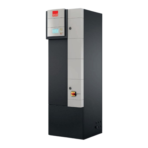
Stulz EC Tower ECD 91 Air Conditioning Manuals
Manuals and User Guides for Stulz EC Tower ECD 91 Air Conditioning. We have
1
Stulz EC Tower ECD 91 Air Conditioning manual available for free PDF download: Technical Manual
Stulz EC Tower ECD 91 Technical Manual (206 pages)
Precision Air Conditioning Units
Brand:
Stulz
| Category:
Air Conditioner
| Size: 19 MB
Table of Contents
Table of Contents
4
Information on this Document
7
Scope
7
Presentation Conventions
7
Safety
7
Safety Instructions
7
Handling Refrigerants
8
Duties of the Operator
8
Other Applicable Documents
9
Residual Risks
10
Transport
12
Delivery of Units
12
Transport / Storage
12
Storage
13
Description
14
Type Code
14
Proper Use
15
Improper Use
15
EC Tower Method of Operation
16
EC Tower Sizes and Versions
20
Sizes
20
Unit Versions
20
Heater Method of Operation
21
Application Limits
22
Technical Data
22
EC Tower Technical Data
24
Electrical Data and Circuit Diagram of EC Tower
27
Dimensional Drawings
28
Operating and Connection Data of EC Tower
29
ECU/D 091 Size 1 - Version 07
29
ECU/D 181 Size 2 - Version 07
31
ECU/D 251 Size 2 - Version 07
33
Installing the EC Tower
35
Setting up
35
Opening the EC Tower
36
Location of Refrigerant Connections
38
Connecting the Pipes
38
Installing the Drain
42
Types of Installation
42
Installing the Refrigerant Circuit
46
Establishing the Conductivity of the Feed Water
47
Connecting the Steam Humidifier to the Feed Water
48
On-Site Preparations
48
Connecting the Downflow Unit to the Feed Water
48
Connecting the Upflow Unit to the Feed Water
50
Electrically Connecting the EC Tower
52
Circuit Diagram
53
Electrical Wiring Diagram
53
Electrically Connecting the EC Tower to Junction Box 1
54
Connecting the Outdoor Unit to the EC Tower
55
Connecting the Outdoor Unit Electrical Supply to Junction Box 1
55
Connecting the Outdoor Unit Signal Lines in Junction Box 2
56
Setting the DIP Switches of the Printed Circuit Boards in Junction Box 2
57
Starting up the EC Tower
59
EC Tower Maintenance
63
Safety Instructions
63
Maintenance Intervals
64
Air Circuit Maintenance
64
Replacing the Filter of Upflow Units
65
Replacing the Filter of Downflow Units
66
Replacing the Filter in the Filtration Box in Downflow Units
69
Unit in General
70
Heater Maintenance
70
Steam Humidifier Maintenance
70
Replacing the Solenoid Valve Coil of the Optional Water Warning System
70
Troubleshooting
71
Troubleshooting the EC Tower
71
Troubleshooting the Heater
72
Troubleshooting the Steam Humidifier
72
Troubleshooting the Optional Water Warning System
72
Dismantling and Disposing of the EC Tower
73
Spare Parts
74
Overview
75
Options
75
Installing the Condensate Pump
78
Safety Instructions
78
Checking the Product Package
79
Other Applicable Documents for Installing and Operating the Condensate Pump
79
Selecting the Installation Location
79
Electrically Connecting the Condensate Pump to EC Tower Size 1
82
Electrically Connecting the Condensate Pump to EC Tower Size 2
84
Installing the Blow-Out Plenum for Upflow Units
87
Installing the Blow-Out Plinth for Downflow Units
88
Installing the Raised Floor Stand
91
Installing the Adapter Panel for Upflow Units
94
Installing the Adapter Panel for Flexible Canvas Fittings or Duct Connections
95
Installing the Duct Connection
95
Installing the Flexible Canvas Fitting
96
Installing the Louver Damper for Upflow Units
98
Installing the Louver Damper
99
Electrically Connecting the Louver Damper
99
Installing the Louver Damper for Downflow Units
100
Installing the Louver Damper
101
Electrically Connecting the Louver Damper
102
Installing the Filtration Box
103
Installing the Temperature and Humidity Sensor B03 for Supply Air
105
Installation Conditions
105
Electrically Connecting the T/H Sensor B03
106
Installation Diagram
106
Installing the Water Warning System
108
Safety Instructions
108
Other Applicable Documents
109
Selecting the Installation Location
109
Water Warning System Versions and Required Components
110
Version 1: Installing a Water Warning System with Sensor, Without Solenoid Valve
112
Version 1 Connection Diagram
113
Option for Versions 1 and 2: Installing the Additional Sensor (B17)
118
Selecting the Installation Location
118
Additional Sensor Connection Diagram
119
Version 2: Installing a Water Warning System with Sensor and Solenoid Valve
121
Version 2 Connection Diagram
121
Option for Versions 1 and 2: Installing the Additional Sensor (B17)
124
Version 3: Installing the BMS Contact for the Water Warning System
125
Version 3 Connection Diagram: BMS Contact for Water Warning System
125
Wib 8000
127
Installation Instructions
127
Technical Data and Dimensions
127
Installing the WIB 8000
128
Connection Diagram for WIB 8000
129
Starting up the WIB 8000
130
Installing the RS485 EBUS Expansion Board
132
Installation Instructions
135
Installing the Front Door for Upflow Units
135
Annex
139
Technical Manual for Comptrol Interface III K for EC Tower
139
Annex
140
Information on this Document
142
Presentation Conventions
142
Scope
142
Target Group
142
Abbreviations
143
Formatting
143
Nomenclature
143
Copyright
144
Disclaimer
144
Liability Claims for Defects
144
Proper Use
144
Safety
144
Other Applicable Documents
145
Required Personnel Qualifications
145
Safety Instructions
145
Analog Input
146
Digital Inputs
146
Digital Outputs
146
Product Description
146
Types of Connection
146
X/Y Remote Control Bus
146
Interface III K Connection Assignment
147
DIP Switch S1
148
DIP Switch S2
148
7-Segment Display
149
Analog Input Functions
149
Direct Frequency Request Via a 0-10 V DC Signal
149
Interface III K Functions
149
Evaluating the Analog Input
150
Forced Mode
150
Functions Via the Digital Inputs
150
Inversion of Digital Outputs
150
Mode Selection (Cooling/Heating/Fan)
150
Remote ON/OFF
150
Special Functions
150
Alarm Signal
151
Status of the Interface III K (Master/Slave)
151
Status Signals
151
Program Overview
152
Configuring the Interface III K for Program 8
153
Description
153
Program 8 - Direct Frequency Request
153
Setting Program 8 on DIP Switch S1
153
For FDC Outdoor Units: Setting DIP Switch S1 on the Interface III K
154
For SRC Outdoor Units: Setting DIP Switch S1 on the Interface III K
154
Setting the Functions for Program 8 on DIP Switch S2
154
Setting the Outdoor Unit Model on DIP Switch S1
154
Analog Input
155
Digital Input Assignment in Program 8
156
Digital Output Assignment in Program 8
156
Connection Diagram for Program 8
157
Initialization
157
Initialization Sequence
157
Starting up the Interface III K
157
Troubleshooting
158
Error Codes
159
Rebooting the System
160
Disposal
161
Technical Data
162
Spare Parts
163
Identification of the Steam Humidifier OEM
164
Steam Humidifier OEM User Manual
164
Data Sheet for Optional Condensate Pump
187
Data Sheet for 72.01 Level Controller
189
Data Sheet for Optional Water Warning System
189
Data Sheet for 72.11 Sensor
190
Data Sheet for Solenoid Valve
191
Data Sheet for Relay K08 and BMS Contact K17
194
Data Sheet for Temperature and Humidity Sensor B03 for Supply Air
196
Installation Instructions for Louver Damper Servo Motor
200
CE Declaration of Conformity for the EC Tower
204
Advertisement
Advertisement
Related Products
Stulz EC Tower ECD 181
Stulz EC Tower ECD 251
Stulz EC Tower ECU 91
Stulz EC Tower ECU 181
Stulz EC Tower ECU 251
Stulz E2 Series
Stulz ENS 18 A
Stulz ESO 4302 ASN
Stulz ESO 4302 ASF
Stulz ESO 7102 ASF
Stulz Categories
Air Conditioner
Humidifier
Chiller
Controller
Computer Hardware
More Stulz Manuals
Login
Sign In
OR
Sign in with Facebook
Sign in with Google
Upload manual
Upload from disk
Upload from URL