Advertisement
PRODUCT PROFILE
SPECIFICATIONS
I
Note:
I
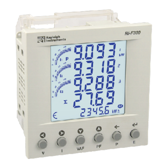
blinks every 5 sec. This indicates energy is being consumed.
ORDER INFORMATION
Outputs
Product
RS485 (Modbus RTU) & Pulse
RI-F 00 -C
3
-*
SERIAL COMMUNICATION
Interface standard and protocol
Communication address
Transmission Mode
Data types
Transmission distance
Transmission speed
Parity
Stop bits
Response time
ACCURACY
Voltage V
±0.5% of F.S.
L-N
Voltage V
±0.5% of F.S.
L-L
Current
±0.5% of F.S.
Frequency
For L-N > 20V,
±0.1% of F.S.
For L-L > 35V
Active Power
1%
Apparent power
1%
Reactive Power
1%
(F.S - Full Scale)
RI-F100-C
RI-F300
96mm x 96mm
Certification
RS
485
AND
MODBUS RTU
1 255
...
Half duplex
Float, Hex and Integer
500 Met
re
maximum
300, 600,1200, 2400, 4800, 9600,
19200 (in bps)
None, Odd, Even
1 or 2
100 ms
(max and independent of baud rate)
±
Power factor
0.01 (Digit)
Active energy
EN50470 : CI.B
Reactive energy
EN62053-23: CI.2
Apparent energy
Class 1
MAX/MIN
1%
Active Power
MAX/MIN
1%
Reactive Power
MAX Apparent Power
1%
MID APPROVAL INSTALLATION NOTES
:
1. The CT ratio must be set before putting the meter
into service.
2. The RJ45 connection between the meter and the
current transformer must be sealed.
CONFIGURATION LOCK PARAMETER DESCRIPTION
NOTE:
Once Programming Mode Is entered The parameters
below will be locked out after 15 Minutes. No further
adjustment is possible without returning to supplier.
Network Selection
CT Primary
Pulse Duration
Factory default
RESOLUTION
PT Ratio x CT Ratio
<15
<150
Example: If CT=100/5A (CT=20) & VT=380:380 (VT=1:1, VT=1), then energy
reading resolution=0.1K (20x1=20) and a pulse will be emitted every 100wh
SAFETY PRECAUTIONS
Safety related
notifications
operating manual or on the equipment must be strictly followed to ensure the
safety of personnel as well as the instrument.
If the equipment is not used in a manner specified by the manufacturer it may
impair the protection provided by the equipment.
Do not use the equipment if there is any mechanical damage.
Ensure that the equipment is supplied with correct voltage.
No repairs, maintenance or adjustments are possible.
CAUTION
1.Read complete instructions prior to installation
2.Risk of electric shock. Only to be installed by competent personnel.
3.The equipment in its installed state must not come in close proximity to any
heating sources, oils, steam, caustic vapours or other unwanted process
by-products.
WIRING GUIDELINES
MID
1.To
prevent
the risk of electrocution
equipment prior to undertaking any work. Always confirm absence of
supply prior to starting work using appropriate voltage detection
equipment.
2.Wiring shall be done strictly according to the terminal layout. Confirm that
all connections are correct
3.Routing of connecting cables shall be away from any internal EMI source.
4 C
. abl
es
used for
voltage and output
2
of 0.5mm to 2.5mm . (20 to14AWG ; 75 C (min) )
5
. Copper cable should be used. ( tranded or
6
.All wiring to
be
in accordance with applicable local standards
CT ROTATION - IMPORTANT NOTE
Please note: All
THREE PHASE
are configured to monitor Incoming supplies (L1 is on the right-hand side
when viewed from the P2 face. If the transformer is to be used for load
monitoring (Requiring L1 to be on the Left-hand side when viewed from
the P2 face), the operator must perform the
described below;
To change:
-3
1. Press
and hold
key. Press and hold the key again for 3 seconds.
2. Wait 5 seconds for meter to resume online reading. Meter display will
show LH when checked using the
below.
To check:
1. Press
and hold
key.
2. Wait 5 seconds and the meter will resume normal operation.
Doc. name : OP INST RI-F 00
PT secondary
Pulse width
PT Primary
Energy Reset
<1500
kWh
0.01K
<15000
0.1K
>15000
, symbols and instructions that appear in this
or
operation of the unit.
, always isolate the power supply to the
before energizing the equipment
connection must have a cross section
s
2
0
s
solid
core cable)
easywire current transformers as default
"To change"
"I" for 3 seconds
until the display changes, release the
"To check"
procedure described
"I" for 3 seconds
until the display changes, release the
3
OP
300
1K
0.01M
0.1M
.
procedure
-V01(Page 1 of 6)
Advertisement
Table of Contents

Related Manuals for Rayleigh Instruments RI-F300


Summary of Contents for Rayleigh Instruments RI-F300
- Page 1 RI-F100-C RI-F300 PRODUCT PROFILE MID APPROVAL INSTALLATION NOTES 1. The CT ratio must be set before putting the meter into service. 2. The RJ45 connection between the meter and the current transformer must be sealed. 96mm x 96mm CONFIGURATION LOCK PARAMETER DESCRIPTION...
-
Page 2: Device Identification
FRONT PANEL DESCRIPTION ONLINE PAGE DESCRIPTION ONLINE PAGE DESCRIPTION The first Screen : Displays import active energy of first phase. There are 6 dedicated keys labeled as V, M kW The second screen : Displays import active energy of second I, VAF, PF, P , E. -
Page 3: Programming Menu
00.01 to 99.99 0.10 Pulse duration INSTALLATION NOTES Factory Default No / Yes CT INPUT - Only Rayleigh Instruments RI-CTxxxEW Easywire Current transformers may be used with Reset Energy and Max Demand No / Yes this meter. 0001 To 9999 0000 VOLTAGE INPUT - This meter is self-supplied from all three phases L-N. - Page 4 MODBUS REGISTER ADDRESSES LIST Readable / writable parameters : [Data Structure : Integer] Range Address Hex Address Parameter Length (Register) 40000 0x00 Password Min value : 0 Max value : 9998 Meaning : 255 40007 0x07 Value : 1 Slave id Meaning : 300 40008 0x08...
- Page 5 MODBUS REGISTER ADDRESSES LIST Readable Parameters : [Length (Register) : 2 ; Data Structure : Float] Address Hex Address Parameter Address Hex Address Parameter Address Hex Address Parameter Voltage V1N Frequency Total kVArh (Imp) 30000 0x00 30056 0x38 30112 0x70 Voltage V2N Total kVArh (Exp) 30002...
-
Page 6: Wiring Information
M kW M kW M kW M kVAr M kVAr M kVAr Rayleigh Instruments Ltd. Raytel House, Cutlers Road, South Woodham Ferrers, Essex, (Specifications are subject to change, since development is a continuous process.) CM3 5WA, UK Tel. 0044(0)1245428500 www.rayleigh.com Doc.
Need help?
Do you have a question about the RI-F300 and is the answer not in the manual?
Questions and answers