Advertisement
Quick Links
Specifica ons
Wiring Input
Rated Input Voltage
Frequency Range
CT Primary
CT Secondary
VT Primary
VT Secondary
Auxiliary / Power consump on
Display Update Rate
Opera ng / Storage Temperature
Humidity
Protec on Degree (IEC/EN60529)
Pulse Output
Pulse Resolu on / Dura on
Communica on
MECHANICAL INSTALLATION
PRODUCT SAFETY
Safety related no fica on, symbols and instruc ons that appear in this
opera ng manual or on the equipment must be strictly followed to
ensure the safety of personnel as well as the instrument. If the
equipment is not used in a manner specified by the manufacturer it may
impair the protec on provided by the equipment
Do not use the equipment if there are mechanical damage
·
Do not exceed the stated maximum ra ngs of the device
·
No repairs, maintenance or adjustments are possible
·
·
Read the complete instruc on manual prior to installa on or
opera ng the unit
The equipment in its installed state must not come into close
·
proximity to any hea ng sources, oils, steam, caus c vapours or
other unwanted process by-products
Do not use in hazardous or classified loca on where explosion or
·
other dangers can be triggered by the device
EO&E: Document subject to change
RI-F200-B-C / RI-F200-G-C
RI-F200-B-MB / RI-F200-G-MB
3Ø 4 wire, 3Ø 3 wire, 2Ø 3 wire, 1Ø 2 wire
3x 11...300V AC (L-N), 19...519V AC (L-L)
45...65Hz
1A/5A...10,000A configurable
1A or 5A (max ra ng x1.2)
100...500kV configurable
100...500V AC (L-L) configurable
100...240V AC (±15%) 45...65Hz / < 8VA
1 sec all parameters
-10...55°C / -20...70°C
0...85% non-condensing
IP54 Front only (rubber gasket fi ed)
External 5...27V DC / 100mA max
0.01...99.99kWh per imp / 0.1...2 sec
Modbus RTU over RS485
MBus (EN13757)
Pulse SO
RTU
Voltage V L-N and V L-L
Current
Frequency for L-N > 20V, L-L > 35V
Ac ve, Reac ve and Apparent Power
Power Factor
Ac ve Energy
Reac ve Energy
Wh Resolu on and Default Pulse Weight
CT Ra o x VT Ra o
<15
Wh / VArh / VAh
0.01k
INT
0.01k
Example
If CT = 100/5A (CT ra o = 20) & VT = 350/350V (VT Ra o = 1)
Wh resolu on = 0.1kWh (20 x 1 = <150) | Pulse O/P default = 0.1kWh/pulse
Installa on & Environmental
Panel mounted, indoor used only.
Installa on category: III (300V L-N)
Al tude: up to 2000 m
Protec on Class: II
Pollu on degree: II
All terminal covers must be fi ed a er wiring
INSTALLATION PRECAUTIONS
Risk of electric shock!
Only to be installed by a competent person
To prevent the risk of electrocu on, always isolate and lock-off the
·
power supply to the equipment prior to undertaking any work
Always confirm absence of electricity prior to star ng work using
·
appropriate voltage detec on equipment
Wiring shall be done strictly according to the terminal layout
·
Confirm that all connec ons are correct before energizing the
·
equipment
Rou ng of cables shall be way from any internal EMI source
·
Copper cable should be used
·
All wiring to be in accordance with applicable local standards
·
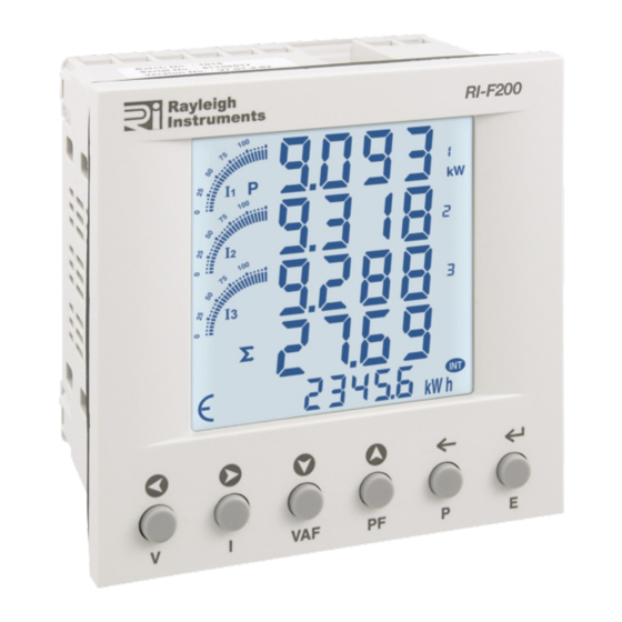
RI-F200
Instruc on Manual
Accuracy
±0.5% of full scale
±0.5% of full scale
±0.1% of full scale
1%
±0.01 of Unity
Class 1 (IEC/EN 62053-21)
Class 2 (IEC/EN 62053-23)
<150
<1500
<15k
0.1k
1k
0.01M
0.1k
1k
0.01M
X 4
<150k
>150k
0.1M
1M
0.1M
0.1M
RI-F200-IM-V01
1
Advertisement

Subscribe to Our Youtube Channel
Related Manuals for Rayleigh Instruments RI-F200


Summary of Contents for Rayleigh Instruments RI-F200
- Page 1 RI-F200 Instruc on Manual Pulse SO RI-F200-B-C / RI-F200-G-C RI-F200-B-MB / RI-F200-G-MB Specifica ons Accuracy Wiring Input 3Ø 4 wire, 3Ø 3 wire, 2Ø 3 wire, 1Ø 2 wire Voltage V L-N and V L-L ±0.5% of full scale Rated Input Voltage 3x 11...300V AC (L-N), 19...519V AC (L-L)
- Page 2 0.8 Nm Modbus / MBus 500m Max, ≤ 32 meters Typical Modbus configura on shown For MBus interface follow Wiring Topology below Wiring Topology A | B Daisy Chain Star Network ü û Modbus MBus 1 | 2 ü ü RI-F200-IM-V01...
- Page 3 Does not reset energy & demand values ü 20 21 Reset Energy No / Yes (Password +1) Once entered, reset each value individually ü 21 22 Reset Demand No / Yes ü 22 23 Reset Auxiliary Switch ON No / Yes ü RI-F200-IM-V01...
- Page 4 INVAL Id: Missing Phase Hold 3 sec RI-F200-IM-V01 Rayleigh Instruments Limited (Head Office) Rayleigh Instruments Limited SP. Z o.o. (European Office) Raytel House, Cutlers Road, South Woodham Ferrers, Chelmsford, Essex. CM3 5WA Ul. Aleje Jerozolimskie 214, Warsaw, Poland, 02-486 W: www.rayleigh.com E: sales@rayleigh.com...
Need help?
Do you have a question about the RI-F200 and is the answer not in the manual?
Questions and answers