True GDM-49-HC-TSL01 Installation Manual
Hide thumbs
Also See for GDM-49-HC-TSL01:
- Installation manual (22 pages) ,
- Installation manual (40 pages) ,
- Installation manual
Table of Contents
Advertisement
TRUE
manufacturing co
CONGRATULATIONS!
You have just purchased the finest commercial refrigerator
available. You can expect many years of trouble-free operation.
TABLE OF CONTENTS
Ownership & Uncrating
Mechanical Temperature Controls Sequence of Operation
WARRANTY
TRUE MANUFACTURING CO., INC.
2001 East Terra Lane • O'Fallon, Missouri 63366-4434
(636)-240-2400 • FAX (636)-272-2408 • INT'L FAX (636)272-7546 • (800)-325-6152
Parts Department (800)-424-TRUE • Parts Department FAX# (636)-272-9471
Web: www.truemfg.com
.,
.
inc
1
2
3
3
5
6
8
9
11
13
13
19
29
30
31
32
33
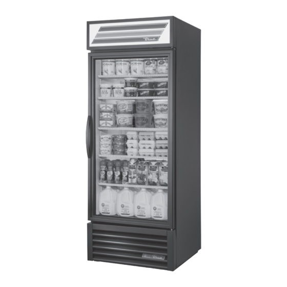
gdm freezer/refrigerator
INSTALLATION MANUAL
gdm freezer
GDM-26-HC~TSL01
GDM-49-HC~TSL01
GDM-69-HC-LD
INSTALLATION MANUAL
/
refrigerator
Advertisement
Table of Contents


Need help?
Do you have a question about the GDM-49-HC-TSL01 and is the answer not in the manual?
Questions and answers