Table of Contents
Advertisement
Quick Links
Haier
Main chipset:MS6488E
This service information is designed for experienced repair technicians only and is not designed for use by the general
public.
It does not contain warnings or cautions to advise non-technical individuals of potential dangers in attempting to
service a product.
Products powered by electricity should be serviced or repaired only by experienced professional technicians. Any
attempt to service or repair
the product or products dealt with in this service information by anyone else could result in serious injury or death.
SERVICE MANUAL
WARNING
Model No.LE75H9000U
© 2013 Qingdao Haier Electronics Co., Ltd.
All rights reserved. Unauthorized copying and
distribution is a violation of law
LED TV
1
Advertisement
Table of Contents

Related Manuals for Haier LE75H9000U


Summary of Contents for Haier LE75H9000U
- Page 1 © 2013 Qingdao Haier Electronics Co., Ltd. All rights reserved. Unauthorized copying and distribution is a violation of law...
-
Page 2: Table Of Contents
Service Manual Model No.: LE75H9000U CONTENTS Chapter 1. General Information 1-1. Document Information ..............4 1-2. General Guidelines..............4 1-3. Important Notice.................4 1-3-1. Follow the regulations and warnings ............4 1-3-2. Be careful to the electrical shock ..............4 1-3-3. Electro static discharge (ESD)..............4 1-3-4. - Page 3 Service Manual Model No.: LE75H9000U Chapter 6. Operation Instructions 6-1. Front Panel Controls..............19 6-2. Back Panel Controls ..............20 6-3. Setting Up Your Remote Control ..........21 Chapter 7. Electrical Parts 7-1. Circuit Diagram................22 Chapter 8. Measurements and Adjustments 8-1. Software Update ................22 Chapter 9.
-
Page 4: Chapter 1. General Information
Service Manual Model No.: LE75H9000U Chapter 1. General Information 1-1. Document Information Document format: Adobe PDF Author: Gaobingbing Compiler: 1-2. General Guidelines When servicing, observe the original lead dress. If a short circuit is found, replace all parts which have been overheated or damaged by the short circuit. -
Page 5: About Lead Free Solder (Pbf)
Service Manual Model No.: LE75H9000U assembly, drain off any electrostatic charge on your body by touching a known earth ground. Alternatively, obtain and wear a commercially available discharging wrist strap device, which should be removed to prevent potential shock reasons prior to applying power to the unit under test. -
Page 6: Ordering Spare Parts
Service Manual Model No.: LE75H9000U Do not connect the test fixture ground strap to any heat sink in this receiver. CAUTION: 9. Remove the antenna terminal on TV and turn on the TV. 10. Insulation resistance between the cord plug terminals and the eternal exposure metal should be more than Mohm by using the 500V insulation resistance meter. -
Page 7: Chapter 2. Specification
Service Manual Model No.: LE75H9000U Warning: A “warning” is used when there is danger of personal injury. Reference: A “reference” guides the reader to other places in this binder or in this manual, where he/she will find additional information on a specific topic. -
Page 8: External Pictures (Four Faces)
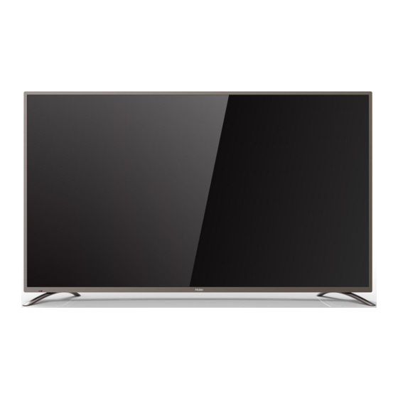
Service Manual Model No.: LE75H9000U 2-2. External pictures (four faces) Front Side... - Page 9 Service Manual Model No.: LE75H9000U Up Side Right Side...
-
Page 10: Chapter 3. Disassemble And Assemble
Service Manual Model No.: LE75H9000U Back Side Chapter 3. Disassemble and Assemble 3-1. LE75H9000U 3-1-1. Remove the Stand 3-1-3. Remove the Mainboard 1. Remove the four screws indicated . 2. Remove the Power Supply Module. 1. Lay down the TV set . -
Page 11: Remove The Remote Control Board
Service Manual Model No.: LE75H9000U 1.Remove the fourteen screws . 2.Flip machine, panel side up. 3.Carefully raise the Front shell from bottom. 3-1-6. Remove the Remote Control Board And the Key Board Remove the Remote Control Board and the Key Board indicated by... -
Page 12: Chapter 4. Location Of Controls And Components
Service Manual Model No.: LE75H9000U Chapter 4. Location of Controls and Components 4-1. Board Location C Panel B Main Board A Power Board Parts Type Description A Board HKL-750203 Power board B Board 20177(6488+6M60) Main board SAMSUNG LSC750FF01 C Panel... -
Page 13: Mainboard
Service Manual Model No.: LE75H9000U 4-2. Mainboard 4-2-1. Function Description Process signal which incept from exterior equipment then translate into signal that panel can display. 4-2-2. Connector definition... -
Page 14: 4-3.Led Panel
Service Manual Model No.: LE75H9000U 4-3. LED Panel LE75H9000U Backlight Unit LVDS Connector... -
Page 15: Led Panel Lvds Interface Connections
Service Manual Model No.: LE75H9000U 4-4. LED Panel LVDS Interface Connections... -
Page 16: Chapter 5. Installation Instructions
Service Manual Model No.: LE75H9000U Chapter 5. Installation Instructions 5-1. Accessories... - Page 17 Service Manual Model No.: LE75H9000U...
-
Page 18: Chapter 6. Operation Instructions
Service Manual Model No.: LE75H9000U Chapter 6. Operation Instructions 6-1. Front Panel Controls... -
Page 19: Back Panel Controls
Service Manual Model No.: LE75H9000U 6-2. Back Panel Controls 6-3. Setting Up Your Remote Controls... -
Page 20: Chapter 7. Electrical Parts
Service Manual Model No.: LE75H9000U Chapter 7. Electrical Parts... -
Page 21: Circuit Diagram
Service Manual Model No.: LE75H9000U Circuit Diagram PL.MS6M60.1 A15371 维修原理图(1).pdf Chapter 8. Software Update Software Upgrade Sequence: 1: 6488+6M60 Software Upgrade. 2: 8.8.9.3 Software Upgrade. 6488+6M60 Software upgrade method: First : 1: Press the Source key , as shown in fig :... - Page 22 Service Manual Model No.: LE75H9000U 3: Select Software update(USB) , Press OK key 1: Enter the HDMI channel. 2: Press the Source key , as shown in fig: 3: Input 8.8.9.3 enter the factory menu . as shown in fig:...
- Page 23 Service Manual Model No.: LE75H9000U 4: Select other , enter the 2 level menu. update TV,Press the OK key...
-
Page 24: Chapter 9. Trouble Shooting
Service Manual Model No.: LE75H9000U Chapter 9. Trouble shooting 9-1.Trouble shooting T.MS6488E.U801 Trouble Shooting.ppt... - Page 25 Service Manual Model No.: LE75H9000U Sincere Forever Haier Group Haier Industrial Park, No.1, Haier Road 266101, Qingdao, China http://www.haier.com Printed in China...
Need help?
Do you have a question about the LE75H9000U and is the answer not in the manual?
Questions and answers