Table of Contents
Advertisement
Quick Links
Model Numbers: MQZCV48N, MQZCV48NE, MQZCV48NE2,
MQZCV48LP, MQZCV48LPE, MQZCV48LPE2
Certified to: CSA/ANSI Z21.88:19 • CSA 2.33:19
and CSA2.17-2017
⚠
WARNING:
FIRE OR EXPLOSION HAZARD
Failure to follow safety warnings exactly could result in serious injury, death, or property damage.
-Do not store or use gasoline or other flammable vapors and liquids in the vicinity of this or any other
appliance.
-WHAT TO DO IF YOU SMELL GAS
• Do not try to light any appliance.
• Do not touch any electrical switch; do not use any phone in your building.
• Leave the building immediately.
• Immediately call your gas supplier from a neighbor's phone. Follow the gas supplier's
instructions.
• If you cannot reach your gas supplier, call the fire department
-Installation and service must be performed by a qualified installer, service agency or the gas
supplier.
INSTALLER: Leave this manual with the appliance.
This appliance may be installed in an aftermarket, permanently located, manufactured home (USA only) or mobile home,
where not prohibited by local codes.
This appliance is only for use with the type of gas indicated on the rating plate. This appliance is not convertible for use
with other gases, unless a certified kit is used.
NOT FOR USE WITH SOLID FUEL
- Installation Instructions -
CONSUMER: Retain this manual for future reference.
For Propane Horizontal installations the venting
must be an additional one foot above the minimum
vertical rise off the flue before going horizontal.
BENTLEY
A Division of R-Co. Inc. 2340 Logan Ave.
Winnipeg, Manitoba Canada R2R 2V3 Ph.: (204) 632-1962
Printed in Canada June 15, 2023 Part# 48ZCV-MAN19
Advertisement
Table of Contents

Related Manuals for Kingsman marquis BENTLEY MQZCV48N

Summary of Contents for Kingsman marquis BENTLEY MQZCV48N
- Page 1 - Installation Instructions - BENTLEY Model Numbers: MQZCV48N, MQZCV48NE, MQZCV48NE2, MQZCV48LP, MQZCV48LPE, MQZCV48LPE2 Certified to: CSA/ANSI Z21.88:19 • CSA 2.33:19 and CSA2.17-2017 ⚠ WARNING: FIRE OR EXPLOSION HAZARD Failure to follow safety warnings exactly could result in serious injury, death, or property damage. -Do not store or use gasoline or other flammable vapors and liquids in the vicinity of this or any other appliance.
- Page 2 IT IS THE RESPONSIBILITY OF THE HOME OWNER TO ENSURE THAT NO ONE TOUCHES A HOT APPLIANCE. • If the barrier becomes damaged, the barrier shall be replaced with the manufacturer’s barrier for this appliance. • Any safety screen, guard, or barrier removed for servicing the appliance, must be replaced prior to operating the appliance.
-
Page 3: Table Of Contents
MQZCV48 Table of Contents INFORMATION Table of Contents……………………………………………………………..............Warnings, Installations, and Operations…………………………………..............Installation Requirements for the Commonwealth of Massachusetts…………………………………………………. Carbon Monoxide (CO) Detector………………………………………………………………………………………….. Pre-installation Questions and Answers…………………………………..............Operations and Maintenance Instructions......................Installations in Covered Outdoor Locations......................Mobile Home/Manufactured Housing Installation……………………............... MQZCV48 Framing Your Gas Fireplace………………………………………………………………………….... - Page 4 MQLOGF48B Burnt Oak Log Set........................... 52-53 RBCB1 Cannonballs……………………………………………………………………………………………………….. MQ Dealer Accessories for MQZCV48……………………………………………………………………………... 55-56 MQLOGF48D Setup………………………………………………………………………………………………………... 57-58 GENERAL INSTALLATION, USE, AND MAINTENANCE MQZCV48 Door Installation………………………………………………………………………………………..... Door and Glass Information……………………………………………………………………………………………….. Gas Line Installation………………………………………………………………………………………………………... Millivolt System, Lighting, and Burner Control…………………………………………………………………………... Lighting Instructions for Millivolt Valve with 7 Day Timer………………………………………………………………. Annual Inspection List.............................
-
Page 5: Warnings, Installations, And Operations
Warnings, Installations and Operations - Installation Regulations This gas appliance must be installed by a qualified installer in accordance with local building codes, or in the absence of local codes, with the current CAN/CSA-B149.1 or .2 Installation Code (in Canada) or the current National Fuel Gas Code Z223.1- NFPA 54 when installed in the United States. -
Page 6: Installation Requirements For The Commonwealth Of Massachusetts
Installation Requirements for the Commonwealth of Massachusetts In the Commonwealth of Massachusetts, the installer or service agent shall be a plumber or gas fitter licensed by the Commonwealth. When installed in the Commonwealth of Massachusetts or where applicable codes; the unit shall be installed with a CO detector per the requirements listed below. -
Page 7: Pre-Installation Questions And Answers
Pre-installation Questions and Answers About curing of the paint Your stove or fireplace has been painted with the highest quality silicone stove paint. This paint dries quickly in 15-20 minutes when first applied at the factory. However, due to the high temperature silicone components, the paint will cure when heat is applied to the appliance as it is first used. -
Page 8: Installations In Covered Outdoor Locations
Authority Having Jurisdiction (AHJ) prior to the indoor gas fireplace being installed. Kingsman and Marquis Direct Vent fireplaces may be installed into outdoor locations provided they are suitably protected from direct water impingement. However, all installation clearances in the appliance manual must be observed. Framing, Clearances to Combustibles, Mantel Heights, Facing Requirements, Venting Installation, etc. -
Page 9: Mobile Home/Manufactured Housing Installation
Mobile Home/Manufactured Housing Installation This Direct Vent System Appliance must be installed in accordance with the manufacturer’s installation instructions and the Manufactured Home Construction and Safety Standard Title 24 CFR, Part 3280, or the current Standard for Fire Safety Criteria for Manufactured Home Installations, Sites, and Communities ANSI/NFPA 501A, and with CAN/CSA Z240 MH Mobile Home Standard in Canada. -
Page 10: Mqzcv48 Framing Your Gas Fireplace
MQZCV48 Framing Your Gas Fireplace This section is intended for qualified installers only. Before beginning, make note of where the gas and electrical accesses are located on the unit. This will streamline the construction process. Furthermore, familiarize yourself with the venting and clearance requirements (see Venting section) for this appliance. -
Page 11: Non-Vented Chase Vs Vented Chase - Choose Your Installation
MQZCV48 – Non-Vented Chase VS Vented Chase - Choose Your Installation FRAMED AS NON-VENTED CHASE: (Fireplace is installed As Shipped, with Ventilation Plates in place.) This is a traditional fireplace installation where the fireplace is built into a non-vented chase. •... -
Page 12: Removal Of Vent Covers For Vented Chase
MQZCV48 – Vented Chase Requirements If using insulation in vented chase (i.e. for outside wall), wall HEAT CANNOT BE DISCHARGED INTO THE board / drywall is required to support all insulation. Vented WALLS, FLOOR, OR CEILING. chase must be clean and free of all debris (i.e. loose insulation, •... -
Page 13: V49Eg Grill Installation
V49EG Grill Installation for MQZCV48 Vented Chase -Option- Ventilation Plates must be removed before installation into a Vented Chase ⚠ Grill openings must be flush within 3/4” of enclosure top. This is to prevent excess heat from becoming trapped in the top of the chase. See Framing section of manual. This Grill Meets Minimum Opening Air Free Requirements. -
Page 14: Vl60Egs Side Grill Installation
VL60EGS Side Grill Installation for MQZCV48 Vented Chase -Option- Ventilation Plates must be removed before installation into a Vented Chase ⚠ BOTH GRILLS MUST BE USED. Grill openings must be within 3/4” of enclosure top. This is to prevent excess heat from becoming trapped in the top of the chase. See Framing section of manual. Required Opening Dimensions: 15-1/4”... -
Page 15: Nailing Tab Guide
ZCV39 / ZCV42 / MQZCV48 Framing- Nailing Tab Guide [Qty]2 Nailing Tabs are located on each side of the front frame. These Nailing Tabs can be used in two ways: 1/2” Drywall Flush with Face of Fireplace – Framing Flush with Face of Fireplace -Fireplace to be covered Fireplace and Combustible Wall to be covered with Non-Combustibles (e.g. -
Page 16: Locating Your Appliance / Fireplace Dimensions
MQZCV48 Locating Your Appliance LOCATION KEY: Flat on Wall Across the Corner As an Island As a Room Divider Flat on Wall Corner Exterior Wall See Mantel Leg Clearances Instruction for the proper placement of fireplace. Island installation with a top vent is possible as long as the horizontal portion of the vent system does not exceed 20 feet (6.1 m). -
Page 17: Framing Dimensions
MQZCV48 Framing Dimensions Determine whether face of fireplace will be: • Flush with finished wall (e.g., for surround, cultured stone, or other noncombustible covering). • Flush with framing (to be covered with concrete board for a Flat Wall appearance). Refer to Nailing Tab Guide section also. These structures are not load bearing. -
Page 18: Framing Dimensions For Non-Vented Chase Built Outside Of Room - Doghouse
MQZCV48 Framing Dimensions for Non-Vented Chase Built Outside of Room Fireplace is installed As Shipped, with Ventilation Plates in place. Determine whether face of fireplace will be flush with framing or finished wall. Refer to Nailing Tab Guide also. NOTE: These structures are not load bearing. No loose Combustibles (wood, wiring, etc.) are allowed inside the Chase area. -
Page 19: Mantel Clearances
MQZCV48 Mantel Clearances Mantel Dimensions are from front face or Non-Combustible Facing Before installing any mantels it is Materials covering fireplace. important to determine the combustibility of its material(s). There are two types of mantels to consider: Combustible and Non-Combustible. Optional Recess 3/4”... -
Page 20: Clearance To Combustibles
MQZCV48 Clearance to Combustibles Clearance to Combustibles MQZCV48 36” [92cm] Front 0” [0cm] Back (from Stand-offs) 0” [0cm] Side (from Stand-offs) 0” [0cm] Floor* NG- 66” [168cm] Propane- 78” [198cm] Minimum Ceiling Height (from bottom of fireplace) 0” [0cm] Top (from Stand-offs) 6”... -
Page 21: Facing Requirements
MQZCV48 Facing Requirements for Non-Vented Chase Fireplace is installed As Shipped, with Ventilation Plates in place. Recommended: Non-Combustible Required: 49-1/2” x 51-1/4” ANY MATERIALS COVERING Non-combustible THE FACE OF THE This is to allow concrete board to be FIREPLACE MUST BE NON- screwed to framing if used. -
Page 22: Framing Dimensions For Vented Chase (Built Outside Of Room) V49Eg Grill
ZCV48 Framing Dimensions for Vented Chase (built outside of room) V49EG Grill Ventilation Plates must be removed before installation into a Vented Chase Grill MUST be located at top of chase. Determine whether face of fireplace will be flush with framing or finished wall. Refer to Nailing Tab Guide also. -
Page 23: Framing Dimensions For Vented Chase With V49Eg -Or- Vl60Egs Grills
MQZCV48 Framing Dimensions for Vented Chase with V49EG -OR- VL60EGS Grills Ventilation Plates must be removed before installation into a Vented Chase Grills MUST be located at top of chase. Determine whether face of fireplace will be flush with framing or finished wall. Refer to Nailing Tab Guide also. -
Page 24: Framing Dimensions For Vented Chase With Open Top
MQZCV48 Framing Dimensions for Vented Chase with Open Top Ventilation Plates must be removed before installation into a Vented Chase Determine whether face of fireplace will be flush with framing or finished -Remove Ventilation Plates- wall. Refer to Nailing Tab Guide also. NOTE: These structures are not See Removal of Vent Covers section. -
Page 25: Framing Dimensions - Recessed Vented Chase - V49Eg -Or- Vl60Egs Grills
MQZCV48 Framing Dimensions - Recessed Vented Chase – V49EG -OR- VL60EGS Grills Ventilation Plates must be removed before installation into a Vented Chase Grills MUST be located at top of chase Determine whether face of -Remove Ventilation Plates- fireplace will be flush with framing or finished wall. Refer to Nailing Tab See Removal of Vent Covers section. -
Page 26: Framing Dimensions - Recessed Vented Chase With Open Top
MQZCV48 Framing Dimensions - Recessed Vented Chase with Open Top Ventilation Plates must be removed before installation into a Vented Chase Determine whether face of fireplace will be flush with framing or finished -Remove Ventilation Plates- wall. Refer to Nailing Tab Guide also. NOTE: These structures are not See Removal of Vent Covers section. -
Page 27: Mantel Clearances- For Vented Chase
MQZCV48 -Mantel Clearances- for Vented Chase Ventilation Plates must be removed before installation into a Vented Chase -Remove Ventilation Plates- See Removal of Vent Covers section. A Combustible Mantel can be placed immediately above the fireplace opening. A Combustible Hearth can be placed immediately below the fireplace opening. -
Page 28: Clearance To Combustibles For Vented Chase
MQZCV48 Clearance to Combustibles for Vented Chase Ventilation Plates must be removed before installation into a Vented Chase 36” [92cm] Front 0” [0cm] Back (from Stand-offs) 0” [0cm] Side (from Stand-offs) *Note: If appliance is installed directly on carpeting or other 0”... -
Page 29: Facing Requirements For Vented Chase
MQZCV48 - Facing Requirements for Vented Chase - Ventilation Plates must be removed before installation into a Vented Chase Unit and Framing can be covered with a combustible i.e., drywall up to the fireplace opening. NOTE: FIREPLACE CHASE MUST BE VENTED AT THE TOP OF THE •... -
Page 30: Electrical Receptacle In A Vented Chase
MQZCV48 – Electrical Receptacle in a Vented Chase ELECTRICAL WIRES IN CHASE MUST BE PROPERLY ATTACHED TO INSIDE WALL OF CHASE. DO NOT RUN WIRES DIRECTLY ABOVE APPLIANCE. Please follow the current CSA C22.1 Canadian Electrical Code or the National Electrical Code; ANSI/NFPA 70 when installed in the United States. An electrical receptacle may be located in the front of a vented chase if the following guidelines are adhered to: •... -
Page 31: Inside Fit Safety Screen Installation
ZCV39 / 42 / 48 Inside Fit Safety Screen Installation (Shipped with unit after September 2022) ZCV39CSS2 / ZCV42CSS2 / ZCV48CSS2 Contents of Kit: [1] Child Safety Screen NOTE: For installation of Surrounds when using Inside Fit Safety Screens, refer to VF Surround Installations in the fireplace manual. -
Page 32: Surround Installation
ZCV 39 / 42 / 48 Surround Installation for Inside Fit Screens- (Shipped with unit after September 2022) ZCV39S1 / ZCV39S1PF / ZCV39S2PF / ZCV42S1 / ZCV42S1PF / ZCV47S1 For S1/ S1PF Surrounds: Place surround face down on protected surface. Bend Top Hook and Lower Mount Tab up 90° from surface. For S2PF Surrounds: Bend down Screen Fold Mount Tabs up 90°... -
Page 33: Basic Finishing For S1 Surround
Basic Finishing for S1 Surround ZCV47S1BL Step 1: Frame Fireplace with nailing tabs oriented as shown. Step 2: Use Drywall to finish face of wall. NOTE: Drywall will be flush with fireplace face. Drywall 4-1/8” MIN Nailing Tab 4” MIN Step 3: Once wall is completely finished, Screen with Surround IMPORTANT NOTE!: If installing tile, brick, or other non-... -
Page 34: Basic Finishing For Mqzcv48Dd Doors
MQZCV48 Basic Finishing for MQZCV48DD Doors Step One: Frame Fireplace with nailing tabs oriented as Step Two: Use Drywall to finish face of wall. shown. NOTE: Wall will be flush with fireplace face. Drywall Fireplace Frame Nailing Tab Step 3: A stone, brick, or other non-combustible border IMPORTANT NOTE! When installing stone, brick, or other may be applied to the wall. - Page 35 ZCV48 Fireplace Opening Required Clearance ZCV48 Fireplace Opening Required Clearance 1/2” Clearance is Required for Door to Open All DD Doors are flush with bottom of appliance. ⚠ NOTE FINISHED AREA IN FRONT OF 1/2” Clearance FIREPLACE (FLOOR, HEARTH, ETC.) is required for MUST BE FLUSH WITH BOTTOM Door to Open...
- Page 36 MQZCV39DD / MQZCV42DD / MQZCV48DD Designer Door Installations Each Kit contains: Back Frame, Front Frame, and Screen. If protruding facing materials (i.e., concrete board, brick or tile) are to be used, refer to Facing Material Dimension Requirements section. Designer Doors require a minimum 1/8”...
-
Page 37: Zcv-Tlk Optional Tile Lip Kit
ZCV-TLK Optional Tile Lip Kit This optional kit can be used as a trim around the fireplace opening. Pieces must be cut to the desired length. Contents of Kit: Qty. [4] Tile Lip pieces 47” long, Qty. [12] screws. Instructions: Refer to the chart below to assist with the installation. -Cut [2] tile lip pieces to height of sides, and [2] to length of top &... -
Page 38: Mqzcv48 - 51Uhs Box
MQZCV48 51UHS Box Included with base model. The 51-UHS is designed for millivolt and IPI units for in-unit installation of the Remote Receiver, Fan Control Module, and the IPI Module. 51-UHS can be inserted & removed from beneath fireplace through access panel opening (Remove glass door first). -
Page 39: Component Locations
TRANSFORMER NOTE: The gas line connection may be made of 1/2” rigid pipe or an Approved Kingsman Flex Connector, such as FP15GC. Since some municipalities have additional local codes, it is always best to consult your local authorities and the current... -
Page 40: Mqzcv48 - Z46Fk Fan Kit Installation
ZCV39 / ZCV42 / MQZCV48 Z46FK Fan Kit Installation ⚠ WARNING The fan can be installed through the side of the fireplace. Electrical Grounding Instructions This appliance is equipped with a three prong (grounding) plug for your protection against If fireplace is already installed, the shock hazard and should be plugged directly into a properly grounded three-prong burner pan must be removed to receptacle. -
Page 41: Fan Speed Control Outside Of Fireplace
Split Receptacle- Fan Speed Control Outside of Fireplace If you plan to locate the variable speed control switch for the fan outside of the fireplace and you require a constant source of AC power inside the unit for another accessory such as lights or an IPI valve system, follow one of the procedures below. -
Page 42: Zcv48Pl Porcelain Liner Installation
ZCV48PL Liner Installation ⚠ WARNING: Failure to position the parts in accordance with these diagrams or failure to use only parts specifically approved with this appliance may result in property damage or personal injury. PARTS LIST: [1] – Back Liner [1] –... -
Page 43: Zcv48Rlt / Zcv48Rlh / Mqzcv48Rlf Liner Installation
ZCV48RLT / ZCV48RLH / MQZCV48RLF Liner Installation PARTS LIST: [1] – Back Liner [1] – Left Side Liner [1] – Right Side Liner ⚠ WARNING: Failure to position the parts in accordance with these diagrams or failure to use only parts specifically approved with this appliance may result in property damage or... -
Page 44: Cutting Liners For Use With Glass Tray
MQZCV48GT Cutting Liners for use with Glass Tray Cut shaded areas off and discard. Liners will sit on top of Glass Tray. -
Page 45: Mqzcv48Gt Glass Tray Setup
MQZCV48GT Glass Tray Setup Parts List: [1] Glass Tray with attached Pilot Shield NOTE: for use with brick liners see next page - Cutting Liners for use with Glass Tray – STEP 1: Remove Log Holder, Ember Tray, and Log Grate. Log Holder Ember Tray Log Grate... -
Page 46: Ulk4 Universal Light Kit
MQZCV48 ULK4 Universal Light Kit ( Optional Accent Lighting Kit) Please follow the current ANSI/NFPA 70 National Electrical Code in the USA and CAN/CSA C22.1 Canadian National Electrical Code in Canada. Contents of Kit: [4] 12V Halogen Lamps Lamp Plate with Insulated Studs & wiring ... - Page 47 Screw Screw Screw Screw Lamp Plate Lamp Setup for MQLOGF48 Oak Log Set , MQLOGF48D Driftwood Log Set: STEP 3: Place Lamps in firebox as shown above. Rear Lamps face back wall of firebox, and front lamps are pointed upward. Attach Lamp Mount Brackets to fireplace with [2] screws at the locations shown. Replace Burner, Ember Plate, and Grate Bar.
-
Page 48: Mqlogf39Bw 7 Piece Birch Log Set
MQZCV48 - MQLOGF39BW 7 Piece Birch Log Set - Must be used with MQBBITS 6 Piece Set Lava Rock NOTE: THESE COMPONENTS ARE SUPPLIED WITH THE FIREPLACE. Insulation Wool Lava Rock Insulation Wool Embers Embers ⚠ WARNING: Failure to position the parts in accordance with these diagrams or failure to use only parts specifically approved with this appliance may result in property damage or... -
Page 49: Mqbbits - 6 Piece Birch Log Bit Set
MQBBITS - 6 Piece Birch Log Bit Set - Must be used with MQLOGF39BW STEP 1: Move Log 5 from the MQLOGF39BW Log Set to the new position shown above. STEP 2: Place Log A from the MQBBITS set diagonally as shown above. STEP 3: Place the remaining Log Bits from the MQBBITS set around the firebox bottom outside of the flame area of the fireplace. -
Page 50: Mqlogf48 Oak Log Set
MQZCV48 MQLOGF48 Oak Log Set ⚠ WARNING: Failure to position the parts in LOG 1 accordance with these diagrams or failure to use only parts specifically approved with this appliance may LOG 3 LOG 2 result in property damage or personal injury LOG 4 *NOTE: THESE ITEMS ARE SUPPLIED WITH THE FIREPLACE:... - Page 51 STEP 4 LOG 6 is placed in front of LOG 2. LOG 7 is in front of LOG 3. LOG 8 hooks onto Grate Bar as shown. Place LOG 8 between the LOG 3 LOG 2 Grate Bars on the right side.
-
Page 52: Mqlogf48B Burnt Oak Log Set
MQZCV48 MQLOGF48B Burnt Oak Log Set *NOTE: THESE ITEMS ARE SUPPLIED WITH LOG 3 THE FIREPLACE: *Lava Rock LOG 9 LOG 4 LOG 2 LOG 8 *Embers LOG 5 LOG 7 LOG 1 *Insulation Wool LOG 6 STEP 2 STEP 1 LOG 1 LOG 3 LOG 2... - Page 53 STEP 5 LOG 9 LOG 8 LOG 7 Place LOG 7, LOG 8, and LOG 9 as shown. ⚠ WARNING: Failure to position the parts in accordance with these diagrams or failure to use only parts specifically approved with this appliance may result in property damage or personal injury...
-
Page 54: Rbcb1 Cannonballs
RBCB1 -Cannonballs- Installation Instructions *Must be used with MQZCV48GT Glass Tray Assorted size and colors. Place randomly as desired inside fireplace. Can be used with MQ Glass, MQ Ember, and / or Lava Rock. Do not place Cannonballs directly on burner ports. If sooting occurs change position of or remove affected objects. -
Page 55: Mq Dealer Accessories For Mqzcv48
Use of any other glass can alter the performance of the unit and is not covered under warranty. Discoloration of glass media may occur if placed on the burner, this is not covered under warranty. Z5GC KINGSMAN DECORATIVE BRONZE GLASS Pilot Area Must Not Be Covered •... - Page 56 MQROCK2, MQROCK3 - Must be used with Glass Tray MQZCV48GT MQ EMBER (shown) can be MQRock2 placed on Burner. MQ Glass can be MQRock3 placed on Burner and Glass Tray. Lava Rock (Supplied with Base Unit). Do not place on Burner. ⚠...
-
Page 57: Mqlogf48D Setup
MQZCV48 MQLOGF48D ⚠ WARNING: Failure to position the parts in accordance with these diagrams or failure to use only parts specifically approved with this appliance may result in property damage or personal injury. *These items are supplied with the fireplace. *Lava Rock *Insulation Wool *Embers... - Page 58 Embers, Lava Rock & Lava Rock on Firebox Insulation Wool on Burner Bottom If Crushed Glass and Light Kit are used, place Glass onto front area of Burner and over left and right rear lights.
-
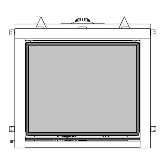
Page 59: Mqzcv48 Door Installation
MQZCV48 Door Installation To install Door: 1. Remove Access Cover below Glass Door. 30° 15° 2. Engage door in lower latches at an angle of between 15 and 30 degrees. 3. Swing door up and pull top latches over door lip at each corner. Door Bottom Latch ⚠... -
Page 60: Door And Glass Information
Door and Glass Information Glass Cleaning It will be necessary to clean the glass periodically. During startup, condensation, which is normal, forms on the inside of the glass, and causes dust, lint etc. to cling to the glass surface. Also, initial paint curing can deposit a slight film on the glass. It is therefore recommended that initially the glass be cleaned two or three times with a fireplace glass cleaner. -
Page 61: Gas Line Installation
NOTE: The gas line connection may be made of 1/2” rigid pressure of 4.5” w.c. must be used for supply from the gas pipe or an Approved Kingsman Flex Connector, such as meter. Consult with the local gas utility if any questions arise FP15GC. -
Page 62: Millivolt System, Lighting, And Burner Control
Millivolt System, Lighting, and Burner Control FOR YOUR SAFETY READ BEFORE LIGHTING WARNING: If you do not follow these instructions exactly, a fire or explosion may result causing property damage, personal injury or loss of life. BEFORE LIGHTING This appliance has a pilot which must be lighted by hand. When Immediately call your gas supplier from a neighbour’s phone. -
Page 63: Lighting Instructions For Millivolt Valve With 7 Day Timer
- Lighting Instructions for Millivolt Valve with 7 Day Timer - FOR YOUR SAFETY READ BEFORE LIGHTING WARNING: If you do not follow these instructions exactly, a fire or explosion may result causing property damage, personal injury or loss of life. •... -
Page 64: Annual Inspection List
Annual Inspection List for Determining Safe Operation of a Direct Vent Gas Fireplace Refer to this checklist for proper maintenance, safe use, and operation. See each section for more specific information. 1. Inspect and operate all pressure relief mechanisms (i.e., relief dampers, spring loaded door latches) installed on your appliance to verify relief mechanisms are free from obstruction to operate. -
Page 65: Troubleshooting The Gas Control System
Troubleshooting the Gas Control System ⚠ WARNING BEFORE DOING ANY GAS CONTROL SERVICE WORK, REMOVE THE GLASS FRONT. NOTE: Before troubleshooting the gas control system, be sure external gas shut off is in the "On" position. Problem Possible Causes Corrective Action Spark igniter will not Defective or misaligned Check for spark at electrode and pilot: if no spark and electrode wire is... -
Page 66: Burner System Maintenance
Burner System Maintenance It is recommended to annually inspect and clean the Burner System to prevent malfunction and / or sooting. This operation should be performed by your dealer or a qualified technician. -CAUTION- Before servicing the burner system ensure that the gas supply is turned OFF and disconnect all electrical connections to the appliance. - Page 67 Gas Conversion Part A MQZCV48 IMPORTANT: Always check for gas leaks with a soap and water solution. DO NOT USE OPEN FLAME FOR LEAK TESTING. Main Burner Air Shutter & Screw Pilot Orifice Main Burner Orifice Brass Nipple Parts List: ...
-
Page 68: Gas Conversion Kit For Top Convertible Pilot Part B
SIT Gas Conversion for Top Convertible Pilot – Part B (series 0190XYZ) Instructions for converting SIT 190 series pilot burner injector from NG to PROPANE and from PROPANE to NG only. This information should be considered as supplemental to the Appliance Manufacturer's Instructions. -
Page 69: Gas Conversion For Modulator - Part C
Gas Conversion for Modulator – PART C... -
Page 70: Burner Removal / Burner System Removal / Installation
MQZCV48 Burner Removal Burner 1. Remove Log Grate. Remove two [2] screws from grate bar assembly. 2. Remove Ember Plate. Remove [2] screws. Ember Plate 3. Remove Burner. Remove four [4] screws from burner. Slide burner to the left and lift to remove. -
Page 71: Ipi Electronic Ignition System
IPI Electronic Ignition System Overview The IPI system is an advanced burner controller that Cover provides you with the option of having either a Standing- Pilot, or an intermittent igniting system. This alternating Backup mode is controlled by the CPI/IPI Switch (Continuous Pilot Battery Ignition/Intermittent Pilot Ignition) located on the IPI System Pack... -
Page 72: Remote Control Operation
Proflame 1 -Remote Control Operation- The Proflame GTM is configured to control the on/off main burner operation, its flame levels, and provides on/off and Smart *thermostatic control of the appliance. Transmitter Remote Receiver Transmitter Room *thermostat ( Transmitter Operation) The Transmitter is powered by 3 AAA type batteries. A Mode The Remote Control can operate as a room *thermostat. -
Page 73: Ipi Electronic Ignition Parts List - Standard System
Proflame 1 -IPI System Parts List- PART NO. DESCRIPTION 1006-P002SI Valve IPI Hi/Lo NG 11. 1002-P012SI IPI Stepper Kit - LP 907.012 1006-P003SI Valve IPI Hi/Lo LP 12. 1002-P013SI IPI Stepper Kit - NG 907.013 13. 1002-P014SI IPI Reg Kit - LP Hi-Lo 907.014 1002-P302SI IPI Ignition Board 14. -
Page 74: Configuration 1: Basic Manual Hi / Lo And Manual Off
Configuration #1: Basic manual HI/LO and manual ON/OFF capabilities. -
Page 75: Configuration 2: Remote On / Off And Manual Hi / Lo
Proflame 1- Configuration #2: Remote ON/OFF and Manual HI/LO Capabilities OPTIONAL: For units with remote HI/LO capabilities, a modulating servo is required to be installed on the valve. The connectors to this servo must be connected to the Remote Harness as shown. SCHEMATIC 1001-P221SI PICTURE... -
Page 76: Operating The Receiver Without Batteries For Gt / Egt / Gtm / Egtm Remote Controls
Operating the Receiver Without Batteries For GT / EGT / GTM / EGTM Remote Controls -Wiring Harness P/N 1002-P906si required for both IPI & Millivolt systems. -Millivolt Systems will also require Power Adapter P/N 1002-P850si. The Remote Receiver & IPI or Millivolt system can be powered by the AC Adapter. This is advantageous if you do not want to use batteries. -
Page 77: Configuration 3: Remote On/Off, Variable Hi/Lo, And Fan
Proflame 1- Configuration #3: Remote ON/OFF, variable HI/LO, and fan capabilities Refer to the fan installation/removal section for fan installation. NOTE: This Configuration is not available on all models of SCHEMATIC fireplace. Check with your dealer. NOTE: Fan Option PICTURE is not available on some models of fireplace. -
Page 78: Electronic Ignition Lighting Instructions
- IPI LIGHTING INSTRUCTIONS - FOR YOUR SAFETY READ BEFORE LIGHTING WARNING: If you do not follow these instructions exactly, a fire or explosion may result causing property damage, personal injury or loss of life. • This appliance is equipped with an ignition device which If you cannot reach your gas supplier, call the fire automatically lights the pilot. -
Page 79: Ipi System
Proflame 2 –NE2 / LPE2 -IPI System Parts List- IPI PROFLAME 2 - COMPONENT PARTS IPI - PF1 and PF2 Common Components PART NO. DESCRIPTION PART NO. DESCRIPTION 1005-P001SI Valve IPI Proflame PF2 885.001 NG - Stepper 13. 1002-P033SI TC - Pilot Burner IPI (Assembled) NG 199.033 1005-P002SI Valve IPI Proflame PF2 885.002 LP - Stepper 14. -
Page 80: Proflame 2 Ifc Module And Remote Control
Proflame 2 IPI - IFC Module and Remote Control Batteries IFC Module Button • Within 10 seconds press the button again until Pairing Remote Control: you hear it beep. • • Install the 3 AAA type batteries in the battery bay, The PF2 Module may now be turned on/off manually located on the base of the Remote Control. -
Page 81: Cold Climates - Cpi Setting - Proflame 2 Remote Control
Cold Climates – CPI Setting - Proflame 2 Remote Control Use the CPI setting during cold weather, otherwise the fireplace may have a hard time starting up and establishing a flame. The CPI (Continuous Pilot Ignition) setting will keep the firebox and fireplace exhaust vent warm during cold weather. -
Page 82: Proflame 2 Remote Control Operation
Proflame 2 Remote Control... - Page 83 Note: When Smart Thermostat is activated, manual flame height adjustment is disabled. (Halogen lights only) Note: This function is only available in Room Thermostat or Smart Thermostat Control Mode.
-
Page 85: Wmbh - Wall Mount Battery Holder- Option
WMBH – Wall Mount Battery Holder – Proflame 1 and 2 IPI Models - Option The WMBH provides the option for a more convenient and accessible location for the backup batteries. NOTE: The WMBH is NOT a remote control receiver. It functions as a Battery Holder and mode selector switch ONLY. ⚠... -
Page 86: Vent Terminal Clearances
Vent Terminal Clearances NOTE: A HORIZONTAL VENT CERTIFIED GUARD (SAFETY CAGE) IS AVAILABLE WHEN REQUIRED BY LOCAL CODES. Clearances are to the edge of the terminal plate. Add 6-3/4” to clearances to arrive at centerline. Local codes or regulations may require different clearances. -
Page 87: General Vent Installation
This gas appliance is approved to be vented either Flex Pipe Venting through the side wall or vertically through the roof. Only Kingsman Flex pipe is shipped in unexpanded length. Kingsman Flex (Z-Flex) Venting Kits and components When installing pipe expand the lengths. Pipe can be specifically approved and LABELED for this appliance expanded to twice their lengths e.g., 4ft to 8ft. -
Page 88: Installation Of Side Wall Venting
MQZCV48 Installation of Side Wall Venting To determine the minimum distance from the bottom of fireplace to center of vent see the Framing Your Gas Fireplace section. Cut a hole through the wall allowing for a 12” x 12” (inside diameter) in combustible walls for wall thimble or a 9” diameter hole in a non-combustible wall (See Figure 2). -
Page 89: Venting Routes And Components
Venting Routes And Components Venting Routes and Components Since it is very important that the vent system maintain its How to Use the Horizontal Vent Table balance between the combustion air intake and the flue gas 1. Determine the height of the system and the number of exhaust, certain limitations as to vent configurations apply and bends required. -
Page 90: Venting Straight Up Through Roof
Venting Straight Up Through Roof An Attic Insulation Shield must be installed where the vent passes from a lower living space into an attic space where the chimney is not enclosed. It is designed to keep insulation materials away from the chimney. When installing the Attic Insulation Shield where the chimney passes from a living space to an attic space, install the shield from below and nail in place using 1"... - Page 91 -Restrictor- Remove for Runs Under 15 Feet Clearances in horizontal venting. Z58VT Clearance to perpendicular wall 24 inches (60 cm). (Recommended to prevent re- circulation of exhaust products. For additional requirements check local codes.) 24” 18” MIN Clearance above highest point of exit on roof 18 inches (45cm) 43ft...
-
Page 92: Venting - Cathedral Ceiling
ZCV39 / 42 / 48 Venting - Cathedral Ceiling Just as with a normal ceiling, an Attic Insulation Shield must be WARNING: HEAT CANNOT BE DISCHARGED installed where the fireplace vent passes from a lower living space into INTO THE WALLS, FLOOR, OR CEILING. Heat must exit through the required 2”... -
Page 93: Approved For Power Vent Pvh58 / Pvh58Fm
Approved for Power Vent PVH58 / PVH58FM - This appliance is approved for use with a Kingsman PVH58 Horizontal Power Vent - A Horizontal Power Vent Termination is intended for use where standard venting configurations are not possible. NOTE: MODELS EQUIPPPED WITH MILLIVOLT/ STANDING PILOT IGNITION: Downward vertical vent runs are NOT permitted. -
Page 94: Pvh58- Pvcm Installation
Bentley ZCV39 / ZCV42 / ZCV48 -PVH58- PVCM Installation FIREPLACE IS SUPPLIED WITH ONE JUNCTION BOX. ADDITIONAL OUTLETS MAY BE REQUIRED. CONSULT A QUALIFIED ELECTRICIAN. MAIN WIRING HARNESS IPI SYSTEM POWER VENT CONTROL MODULE DOUBLE POLE SWITCH MV SYSTEMS ONLY MAIN WIRING HARNESS NOTE: Fireplace glass door must be removed to... -
Page 95: Pvh58 / Pvh58Fm Parts List
Power Vent Parts List – 5/8 Venting NUMBER DESCRIPTION PVH58 Horizontal Power Vent Starter Kit ‐ Exterior Mount PVH58FM Horizontal Power Vent Kit ‐ Flush Mount Note: Must use a one foot section of 5/8 DV hard pipe to connect to the Power Vent Termination (not supplied) CHOOSE CONTROL MODULE OR HARNESS DEPENDENT ON VALVE SYSTEM PVC58MV Power Vent Control Module ‐... -
Page 96: Parts Lists
MQZCV48 Parts List MQEMBER Glowing Embers Part Number Description ZG5C Decorative Ember Glass –Bronze 5LB Fireplace Part Numbers MQG5W Decorative Glass 1/2” White 5LB MQZCV48N (Millivolt) Fireplace Heater rated, NG, MQG5A Decorative Ember Glass Cobalt Blue Tempered Glass, Safety Screen MQZCV48NE (IPI) Fireplace Heater Rated NG, MQG5B... - Page 97 1001-P713SI Pilot Burner LP 199.713 TC SIT FP15GC Stainless Steel Gas Connector 1001-P714SI Pilot Burner NG 199.714 TC SIT Kingsman Fireplace Venting Remote Control / Millivolt Z58DFA M&G-Duravent Adapter (5 x 8) GFRC Remote Control Millivolt / IPI – On/Off...
-
Page 98: Limited Lifetime Warranty
During the first year after installation of the appliance, we will provide a replacement for any component part of your unit found to be defective in materials or workmanship, including labour costs. Repair work requires prior approval by Kingsman, labour costs are based on a predetermined rate schedule and any repair work must be done through an authorized Kingsman dealer.
Need help?
Do you have a question about the marquis BENTLEY MQZCV48N and is the answer not in the manual?
Questions and answers