Advertisement
Quick Links
Advertisement

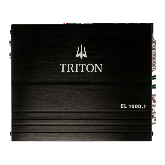
Summary of Contents for Triton EL1000.1
- Page 1 EL SERIES AMPLIFIERS EL10001...
- Page 2 To make sure your new amplifier performs its best, we strongly recommend you have your new Triton amplifier professionally installed. Please use your new Triton amplifier responsibly. Listening to very loud music for extended periods of time can cause permanent hearing loss.
- Page 3 Specifications Model EL10001 Peak Power 1000W Power RMS 2Ω @ 14.4V 500W Power RMS 4Ω @ 14.4V 240W THD+N @ Nominal Power 600W THD+N @10% Nominal Power: 20Hz ~ 150Hz Frequency Response (-3db) 90dB 0.2 ~ 6V Input Sensitivity 50Hz ~ 150Hz Low Pass Filter Damping factor (Nominal Impedance @ 100Hz) 9V ~16V...
- Page 4 III. Installation Preparation Please read the entire manual before installation. Due to the technical nature of amplifiers it is highly recommended that your amplifier is installed by a professional installer or an authorized dealer. Before You Start 1. Disconnect negative battery terminal. (Consult a qualified technician for instructions) 2.
- Page 5 III. Installation Connection Descriptions NOTE: Be sure to follow specific instructions included with your amplifier installation kit (not included with this amplifier). The information below should be used as a general guideline only. Power Wire (+12V) 1. Disconnect negative battery terminal before proceeding. Consult a qualified technician for instructions if you are unsure.
- Page 6 III. Installation Audio Inputs and Controls 1 Line In/Line Out (RCA) 5 Phase Switch 2 High-Level Inputs (Speaker Wire) 6 Crossover Control 3 Gain 7 Remote Bass Control 4 Bass Boost 8 Protect & Power LEDs Power and Speaker Connections 1 Ground Connection 4 Fuse(s) 2 Remote Turn On...
- Page 7 III. Installation Typical Wire Routing Fuse Rating Power/Ground Wire Size When replacing fuses make sure new fuse For optimum performance use only the wire is the correct type and amperage. Using an size listed below or larger. Make sure to use incorrect fuse could damage the amplifier.
- Page 8 III. Installation Amplifier Connections 2 Speakers (stereo) Speakers (bridged) Speaker Connection Connect speaker wires observing polarity. The minimum impedance load for the amplifiers is 2 ohms stereo and 4 ohms bridged. Use of loads lower than these is not recommended and may cause amplifier damage.
- Page 9 III. Installation Configuration/Setup Input level Control The input level control (gain) is used to obtain the best possible match between the head unit audio output and the amplifier input. Begin by turning the input level control fully counterclockwise. Next, turn up the head unit volume control around 3/4 of the way up.


Need help?
Do you have a question about the EL1000.1 and is the answer not in the manual?
Questions and answers