
Related Manuals for Lacertosus PRO POWER ARMS 2.0


Summary of Contents for Lacertosus PRO POWER ARMS 2.0
- Page 1 Istruzioni in lingua italiana. ATTENZIONE: Prima di iniziare ad assemblare o usare il prodotto, leggere il manuale con la massima attenzione e tenerlo sempre a portata di mano vicino all’attrezzo.
-
Page 2: Manutenzione
Grazie per aver scelto un altro prodotto di qualità firmata Lacertosus , goditi l’installazione e qualora dovessi ® riscontrare problemi ti preghiamo di contattarci all’indirizzo info@lacertosus.com. E se pensi che questo manuale non sia abbastanza Scannerizza il codice QR per accedere alle... - Page 3 NON usare mai l’attrezzo se danneggiato, con parti smontate o bulloneria non serrata. Per eventuali riparazioni o richiesta di parti di ricambio, rivolgersi a info@lacertosus.com. Quando l’attrezzo dispone di parti mobili, prestare la massima attenzione durante l’utilizzo per evitare schiacciamenti alle dita, ferite alle mani o altre lesioni alle parti del corpo.
- Page 4 Qualora ciò si verifichi, si fa notare che la modifica riguarda prevalentemente aspetti estetici e che la sicurezza e le informazioni sul prodotto restano comunque garantiti. Per massimizzare l’esperienza di utilizzo e la qualità dei propri prodotti, Lacertosus si impegna a perseguire una politica di costante ®...
- Page 5 L’attrezzo acquistato presenta parti mobili che durante l’uso possono comportare rischi e pericoli in caso di impiego inopportuno senza seguire le procedure di utilizzo e montaggio secondo le istruzioni fornite e con le dovute cautele. L’illustrazione riportata elenca le parti mobili e le zone del prodotto che possono comportare dei rischi alla sicurezza dell’utilizzatore ed altri utenti, cose o animali nei dintorni, per i quali occorre prestare la massima attenzione.
- Page 6 Rimuovere con attenzione il prodotto dalla scatola. Disporre tutti i componenti e controllare che tutte le parti siano presenti e non danneggiate. In caso di parti assenti o danneggiate, contattare l’indirizzo info@lacertosus.com. Il prodotto viene imballato smontato in più parti in maniera da occupare poco spazio; per poter utilizzare il prodotto occorre montarlo riferendosi ai passaggi mostrati nelle pagine successive.
- Page 7 Vite t.bombata con cava esag. M10*25 Chiave a brugola n 3, 5, 6 (coppie) [cm] Rondella Ø10.5*Ø30 Chiave n 16, 18 (coppie) Rondella elastica Ø10 Mazzuola gommata Boccola in acciaio Perno filettato M10 Dado autobloccante M10 x 12 Grano filettato M6*6...
- Page 8 nome qntà Carrello di movimentazione Maniglia di sollevamento Perno di bloccaggio angolare Perno di bloccaggio carrello Rulli di scorrimento Piastrina di centraggio Pomello di serraggio Maniglia di sollevamento Braccio basculante Ghiera filettata Rondella in plastica Ø31*Ø50 Maniglia di allenamento Perno zigrinato di serraggio Tampone ammortizzante Occhiello per belt squat Ruota di scorrimento...
- Page 9 Il prodotto pro power arms 2.0 per la gamma pro arriva preassemblato in alcune parti per facilitare l’installazione da parte dell’utente e ridurre i tempi di montaggio.
- Page 10 Installare il carrello di movimentazione [1] al palo frontale del rack, avendo accortezza che la maniglia di sollevamento [8] sia rivolta verso l’interno, e bloccarlo in posizione in corrispondeza del foro 1 attraverso il perno di bloccaggio del carrello [4]. Avvitare nell’apposito foro il pomello di serraggio [7] senza stringerlo.
- Page 11 Installare la piastrina di centraggio [6], inserendola all’interno delle quattro scanalature laterali del carrello di movimentazione [1], e centrarla in posizione facendo passare il perno di bloccaggio del carrello [4] all’interno del suo foro. In seguito fissare in posizione la piastrina [6] avvitando in modo x2 x2 simmetrico(*) i grani filettati già...
- Page 12 Una volta terminata l’installazione dei due rulli di scorrimento [5] e della piastrina di centraggio [6], effettuare una prima verifica della fluidità di scorrimento del carrello per accertarsi che tutti e quattro i rulli aderiscano al palo del rack rotolando in modo fluido ed evitando giochi tra le parti. Per effettuare tale controllo, sarà...
- Page 13 Riportando il carrello al foro 1 del palo del rack, rimontare il braccio basculante [9] all’interno del carrello di movimentazione, inserendo il perno d’acciaio e l’opportuna bulloneria precedentemente rimossa al punto 1. Stringere bene le viti. NOTA: x2 x1 x2 x2 x2 Per favorire l’azione di centraggio del braccio basculante con il foro del carrello, è...
- Page 14 Una volta terminata l’installazione del braccio basculante [9], effettuare una seconda verifica della fluidità di scorrimento del carrello ripetendo i passaggi visti nel punto 4. Successivamente verificare la fluidità di movimento del braccio basculante, sollevandolo e facendolo ritornare liberamente alla posizione di partenza.
- Page 15 Fissare il carrello all’altezza desiderata (*) attraverso il perno di bloccaggio [4] ed inserire all’altezza voluta la maniglia di allenamento [12] sul braccio basculante [9] fissandola ad esso mediante il perno zigrinato di serraggio [13] ed avvitando al perno superiore della maniglia l’anello in plastica [11] e la ghiera filettata [10].
- Page 16 Il carrello di movimentazione presenta sui lati una serie di fori passanti contrassegnati da un gruppo di cifre indicanti gli angoli ai quali è possibile bloccare, attraverso il perno, in modo fisso il braccio basculante per eseguire esercizi quali dip o trazioni(*).
- Page 17 Scegli la tua configurazione di allenamento e goditi la tua nuova attrezzatura! NOTA IMPORTANTE: Il braccio basculante è caratterizzato dallo stesso tubolare del rack ed i fori sono alla stessa distanza. Questa peculiarità, insieme alla solida struttura costruttiva permettono ai PRO POWER ARMS 2.0 di essere compatibili con tutta la gamma degli accessori per serie PRO permettendoti di allenarti...
- Page 18 Per sfruttare completamente e in sicurezza le nuove PRO POWER ARM 2.0, queste sono da utilizzare insieme alle SAFETY ARMS (PR-P-SA) soprattutto nei casi in cui si lavori con uno starting point diverso, con alto carico, in prossimità della ripetizione massimale o in previsione di allenamenti estenuanti a cedimento. Per tale motivo all’interno della confezione è...
- Page 19 - Lubrificare le parti rotanti tramite lubrificante LC-400. In occasione di controlli periodici: - Sostituite immediatamente qualsiasi pezzo deteriorato, previo contatto del centro assistenza tramite info@lacertosus.com. In caso di inutilizzo prolungato: - Tenere il prodotto in un luogo al riparo da polvere e umidità.
- Page 20 © 2022 Lacertosus SRL | Lacertosus ® is a registered trademark | info@lacertosus.com release date 11/2022 rev.0 11/2022...
- Page 21 Instructions in English ATTENTION: Before starting to assemble or use the product, read the manual carefully and always keep it close at hand near the product.
- Page 22 Thank you for choosing a quality product signed by Lacertosus , enjoy the installation and if you encounter any ® problems, please contact us at info@lacertosus.com. And if you think this manual is not enough Scan the QR code to...
- Page 23 NEVER use the tool if damaged, with parts disassembled or loose nuts. For any repairs or requests for spare parts, please contact info@lacertosus.com. When the tool has moving parts, take the utmost care during use to avoid crushing fingers, hand injuries or other injuries to body parts.
- Page 24 Should this occur, it should be noted that the change mainly concerns aesthetic aspects and that safety and product information remain guaranteed in any case. To maximize the user experience and the quality of its products, Lacertosus undertakes to pursue a policy of constant development ®...
- Page 25 The purchased tool has moving parts which, during use, can pose risks and dangers in the event of inappropriate use without following the use and assembly procedures according to the instructions provided and with due caution. The illustration shown lists the moving parts and the areas of the product that can pose risks to the safety of the user and other users, things or animals in the surrounding area, for which the utmost attention must be paid.
-
Page 26: Environment Characteristics
Carefully remove the product from the box. Arrange all components and check that all parts are present and undamaged. In case of missing or damaged parts, contact info@lacertosus.com. The product is packed disassembled into several parts so as to take up little space; in order to use the product, it must be assembled by referring to the steps shown on the following pages. - Page 27 Button head screw with hex socket M10*25 Allen key #3, 5, 6 (pairs) [cm] Washer Ø10.5*Ø30 Key 16, 18 (pairs) Spring washer Ø10 Mallet Steel bushing M10 threaded pin M10 self-locking nut x 12 M6*6 threaded grain...
- Page 28 nome qnty Handling cart Lifting handle Angle selection pin Carriage locking pin Scroll rollers Centering plate Locking knob Lifting handle Swinging arm Threaded ring Plastic washer Ø31*Ø50 Training handle Knurled locking pin Shock absorbing pad Belt squat loop Handling wheel Protection for safety arm* *To be mounted on the end of the safety arms as shown on page 18...
- Page 29 The pro power arms 2.0 product for the pro range arrives pre-assembled in some parts to facilitate installation by the user and reduce assembly times.
- Page 30 Install the handling cart [1] on the front post of the rack, making sure that the lifting handle [8] is turned inwards, and lock it in position in correspondence with hole 1 using the trolley locking pin [4] . Screw the tightening knob [7] into the appropriate hole without tightening it. x2 x2 As shown in the figure, insert a sliding roller on bearings [5] into the lower holes of the carriage, paying attention to pass the threaded pin inside the metal bushings.
- Page 31 Install the centering plate [6], inserting it inside the four lateral grooves of the handling carriage [1], and center it in position by passing the locking pin of the carriage [4] inside its hole. Then fix the plate [6] in position by screwing symmetrically (*) the threaded grains already present inside the side plates of the carriage [1] as shown in x2 x2 the figure.
- Page 32 Once the two sliding rollers [5] and the centering plate [6] have been installed, carry out a first check of the sliding fluidity of the trolley to make sure that all four rollers adhere to the rack pole by rolling smoothly and avoiding games between the parties. To carry out this check, it will be necessary to remove the locking pin of the carriage [4], placing it on a comfortable grip such as the multifunction rubberized hook (#HK01), with both hands grasp the lifting handles [2] [8] and let slide the carriage all the way up the rack post while visually verifying that all...
- Page 33 Returning the trolley to hole 1 of the rack pole, reassemble the tilting arm [9] inside the handling trolley, inserting the steel pin and the appropriate nuts and bolts previously removed in point 1. Tighten the screws well. NOTE: x2 x1 x2 x2 x2 To facilitate the centering action of the tilting arm with the hole in the carriage, it is possible to use the angular locking pin [3] by inserting it in...
- Page 34 Once the installation of the tilting arm [9] has been completed, carry out a second check of the sliding fluidity of the carriage by repeating the steps seen in point 4. Then check the fluidity of movement of the rocker arm, lifting it and making it return freely to the starting position.
- Page 35 Fix the trolley at the desired height (*) using the locking pin [4] and insert the training handle [12] on the tilting arm [9] at the desired height, fixing it to it using the knurled locking pin [13] and screwing the plastic ring [11] and the threaded ring [10] to the upper pin of the handle.
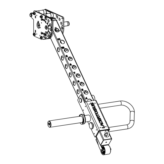
- Page 36 The handling trolley has a series of through holes on the sides marked by a group of numbers indicating the angles at which it is possible to lock the swing arm in a fixed way through the pin to perform exercises such as dips or tractions (*). If you decide to use the pin as a starting point selector, add an angle of about 50°...
- Page 37 Choose your training setup and enjoy your new training gear! IMPORTANT NOTE: The tilting arm is characterized by the same tubular as the rack and the holes are at the same distance. This peculiarity, together with the solid construction structure, allow the PRO POWER ARMS 2.0 to be compatible with the entire range of accessories for the PRO series, allowing you to train with the...
- Page 38 To fully and safely exploit the new PRO POWER ARM 2.0, these are to be used together with the SAFETY ARMS (PR-P- SA) especially in cases where you work with a different starting point, with high load, near the maximum repetition or in anticipation of exhausting workouts to failure.
- Page 39 - Lubricate the rotating parts with LC-400 lubricant. During periodic checks: - Immediately replace any damaged piece, after contacting the assistance center via info@lacertosus.com. In case of prolonged non-use: - Keep the product in a place away from dust and humidity.
- Page 40 © 2022 Lacertosus SRL | Lacertosus ® is a registered trademark | info@lacertosus.com release date 11/2022 rev.0 11/2022...
Need help?
Do you have a question about the PRO POWER ARMS 2.0 and is the answer not in the manual?
Questions and answers