Advertisement
Quick Links
Advertisement

Related Manuals for Lacertosus LM-SA2


Summary of Contents for Lacertosus LM-SA2
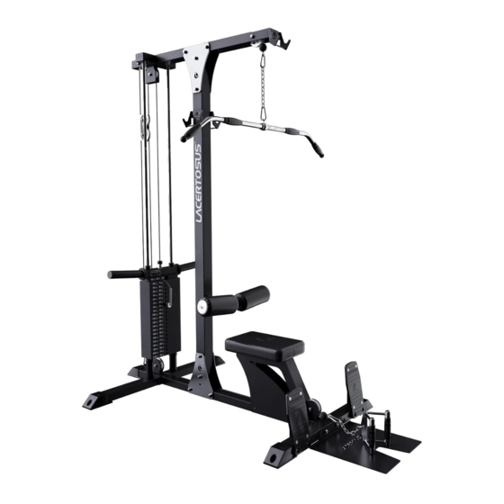
- Page 1 Lat Machine Stand Alone 2.0 LM-SA2 - 1 -...
-
Page 2: Exploded Drawing
EXPLODED DRAWING - 2 -... -
Page 3: Parts List
PARTS LIST NO. DESCRIPTION Q'TY NO. DESCRIPTION Q'TY Rear Bass Frame Leg Cushion Top Frame Rubber Pedal Base Frame Rubber Bumper Upright Frame Big Rubber Bumper Pedal Frame Rubber Feet Front Base Tubing Rubber Cushion Weight Plate Frame End Cap 50*50*75 Foam Frame Plug Cap Weight Stack Frame... - Page 4 ASSEMBLY STEP 1 Install Guide Rod (17) to Rear Bass Frame (1) using 2 pieces Hex Bolt M10*25 (45) as drawing. STEP 2 Assemble Rear Bass Frame (1), Base Frame(3) and Front Base Tubing(6) using 4 pieces Hex Bolt M12*100(49),8 pieces Flat WasherΦ13.5*Φ24*2.5(12) and 4 pieces Nut M12(44) as drawing. - 4 -...
- Page 5 STEP 3 Weight Stack Frame(9), Big Rubber Bumper(33), Weight Stack(19), Top Weight Stack(18) and Weight Plate Frame(7) on Guide Rod (17) in turn, then fixed Weight Plate Frame(7) to Top Weight Stack(18) using 2 pieces Flat WasherΦ11*Φ20*2(40) and 2 pieces Round Head Hex Bolt M10*20(52) as drawing. STEP 4 Assemble Top Frame (2), Base Frame (3), Upright Frame (4), Top Connect Plate (13), Side Connecting Plate (16) and Guide Rod (17) using 2 pieces Flat WasherΦ10.5*Φ30*2.5(41), 16...
- Page 6 STEP 5 Take Top Cable Assembly (27) and Lower Cable Assembly (28) through Long Pulley Bracket (15); Bolted the perforated bolt on the Top Cable Assembly (27) to Selectorized Rod (20), and connect the other end of Top Cable Assembly (27) in turn with the Carabineer Φ8*80(39), ChainΦ5*230(24) , Carabineer Φ8*80(39) and High Pulley Handle(25) as drawing;...
- Page 7 STEP 6 Install Pedal Frame (5) to the required position on the Front Base Tubing (6) using Flat WasherΦ13.5*Φ24*2.5(42), Nut M12 (44) and Pan Head Hex Bolt M12*95(57);Install Hook (10) to the correct postion on the Top Frame(2) and Upright Frame(4) as drawing. STEP 7 Install Foam Frame Assembly (8) to Upright Frame (4) using Flat WasherΦ13.5*Φ24*2.5(42), Nut M12 (44) and Hex Bolt M12*70(48), then adjust the required position in Knob (11);Install Seat...
Need help?
Do you have a question about the LM-SA2 and is the answer not in the manual?
Questions and answers