
Related Manuals for Renogy Pro Series


Summary of Contents for Renogy Pro Series
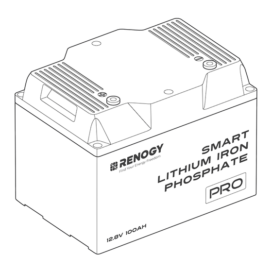
- Page 1 RENOGY Pro Series Smart Lithium Iron Phosphate Battery 12.8V 100Ah VERSION A0 RBT12100LFP-BT USER MANUAL...
- Page 2 Renogy is not responsible or liable for any failure, damage, or injury resulting from repair attempts by unqualified personnel, improper installation, or inappropriate operation.
-
Page 3: Table Of Contents
Step 4. Install Battery Terminals ....................7 Step 5. Connect the Battery to Other Devices ................7 How to Connect Renogy Pro Batteries in Parallel? ...............8 Calculate Voltage and Current in Parallel Connections ............... 8 Balance Batteries Prior to Connection ....................9 Parallel Connection —... -
Page 4: Symbols Used
NOTE: Indicates an important step or tip for optimal performance. Introduction The Renogy Pro Series 12.8V 100Ah Smart Lithium Iron Phosphate Battery adopts a proprietary battery housing material in a smaller size for your RV application. Weighing only half of the lead-acid counterparts, the battery can be safely discharged to 100% Depth of Discharge (DOD), delivering twice the energy. -
Page 5: What's In The Box
What’s In the Box? Renogy Pro Series 12.8V 100Ah RENOGY Pro Series Smart Lithium Iron Phosphate Battery Smart Lithium Iron Phosphate Battery × 1 12.8V 100Ah VERSION A0 RBT12100LFP-BT USER MANUAL User Manual × 1 M8*1.25*12 mm M8*1.25*16 mm Terminal Bolts × 2 Long Terminal Bolts ×... -
Page 6: Get To Know Smart Lithium Iron Phosphate Battery
Get to Know Smart Lithium Iron Phosphate Battery █ Top Positive Terminal (M8) Lift Handle Negative Terminal (M8) Lift Handle █ Bottom Mounting Holes (for Battery Fix Bracket) Mounting Holes (for Battery Fix Bracket) — 3 —... -
Page 7: Dimensions
Dimensions 10.6 in (268 mm) 7.6 in (193 mm) 8.1 in (205 mm) 26.9 lbs. (12.2 kg) Weight Dimension tolerance: ±0.2 in (0.5 mm) How to Size Battery Adapter Cables? Use appropriately sized Battery Adapter Cables (sold separately) based on expected load. Refer to the table below for copper cable ampacities with different gauge sizes. -
Page 8: Secure The Battery (Optional)
Phillips (with 8 M4*10 mm Fix Bolts) Screwdriver (#2) Recommended components marked with “*” are available on renogy.com. Alternative mounting methods are allowed to meet the requirements of specific applications. Choose proper mounting screws specific to your installation site. This manual takes self- tapping screws for wooden walls as an example. -
Page 9: Step 1. Plan A Mounting Site
Step 1. Plan a Mounting Site For optimal battery performance, it is recommended to install the battery in a clean, cool, and dry location, free from any accumulation of water, oil, or dirt. Accumulation of such materials on the battery can lead to current leakage, self-discharge, and even short-circuiting. Vent KEEP DRY FRAGILE... -
Page 10: Step 4. Install Battery Terminals
Step 4. Install Battery Terminals Terminal Bolts Spring Washer Flat Washer 70.8 in·lbs (8 N·m) Battery Battery Adapter Adapter Cable Cable Ensure the cable lug and the top surface of the terminal are in contact, and place the washers on top of the lug. Do not place the washers between the battery terminal and the cable lug to avoid high resistance and excessive heating. -
Page 11: How To Connect Renogy Pro Batteries In Parallel
█ For Batteries in Parallel Inverter DC-DC Charger DC Distribution Charge Panel Controller Battery Fuse How to Connect Renogy Pro Batteries in Parallel? Calculate Voltage and Current in Parallel Connections 12V (12.8V) 400Ah 12.8V 100Ah 12.8V System Voltage System current... -
Page 12: Balance Batteries Prior To Connection
Balance Batteries Prior to Connection Before connecting batteries in parallel, it is important to balance them to reduce voltage differences and optimize their performance. Follow these three steps: Step 1: Charge each battery individually to its full capacity using a suitable charger. DC-DC Charger Battery Fuse Charge Controller... -
Page 13: Parallel Connection - Installation Steps
Parallel Connection — Installation Steps You can choose suitable busbars in parallel connections. Busbars help handle high currents and are typically arranged in a parallel or stacked configuration to distribute electrical power efficiently. Note that the cable connection methods provided below are for reference purposes only, as the optimal approach may vary depending on the specific situation. -
Page 14: Remote, 24/7 Monitoring Via Dc Home App
Step 1: Download the DC Home app. Login to the app with your account. DC Home App Step 2: Pair the battery with the DC Home app. Monitor and modify the parameters of the battery via the app. My Renogy HUB Mode Searching for device Time remaining Please make sure: 1. -
Page 15: Battery Charging And Discharging Logic
Battery Charging and Discharging Logic The battery may be received at a partial state of charge (SOC) depending on the time between manufacturing and shipping. It is crucial to fully charge the battery before its initial use. In case the battery shuts off due to low SOC, promptly disconnect it from loads and charge it to prevent irreversible damage. -
Page 16: How To Estimate The Battery Soc
How to Estimate the Battery SOC? The SOC values listed below are estimated based on the open circuit voltage when the battery is at rest for 30 minutes, not in charging or discharging state. Open Circult Voltage Open Circult Voltage 100% 13.6V 12.9V... - Page 17 Battery Operating Status Condition (For Reference Only) Trigger Battery Temperature ≤ 32°F (0°C) Charge Low Temperature Protection Recover Battery Temperature ≥ 37°F (3°C) Trigger Battery Temperature ≤ -4°F (-20°C) Discharge Low Temperature Protection Recover Battery Temperature ≥ 1.4°F (-17°C) Trigger Charge Current ≥...
-
Page 18: Troubleshooting
Disconnect the battery from the charging triggered due to too high battery during source or loads as soon as possible. current passing through the charging or battery. discharging. For further assitance, contact Renogy technical support service at https:/ /www.renogy. com/contact-us. — 15 —... -
Page 19: Specifications
Specifications General Battery Cell Type Lithium Iron Phosphate Rated Capacity (0.5C, 25°C) 100Ah Nominal Voltage 12.8V Voltage Range 10V to 14.8V Cycle Life (0.5C, 25°C) 5000 Cycles (80% DOD) Dimension 10.6 x 7.6 x 8.1 in / 268 x 193 x 205 mm Weight 26.9 lbs. -
Page 20: Maintenance & Storage
Maintenance & Storage Inspection Please perform regular inspections following the steps below: z Examine the external appearance of the battery. The housing and terminals of the battery shall be clean, dry, and free of corrosion. z Check battery cables and connections. Replace any damaged cables and tighten any loose connections. -
Page 21: Important Safety Instructions
Important Safety Instructions Renogy accepts no liability for any damage caused by: z Force majeure including fire, typhoon, flood, earthquake, war, and terrorism. z Intentional or accidental misuse, abuse, neglect or improper maintenance, and use under abnormal conditions. z Improper installation, improper operation, and malfunction of a peripheral device. -
Page 22: Renogy Support
Questionnaire Investigation To explore more possibilities of solar systems, visit Renogy Learning Center at: renogy.com/learning-center For technical questions about your product in the U.S., contact the Renogy technical support team through: renogy.com/contact-us 1(909)2877111 For technical support outside the U.S., visit the local website below: Canada ca.renogy.com... - Page 23 FCC Statement This device complies with Part 15 of the FCC Rules. Operation is subject to the following two conditions: (1) This device may not cause harmful interference. (2) This device must accept any interference received, including interference that may cause undesired operation.
- Page 24 Save 105 gallons of water from being consumed Renogy Power PLUS Renogy Power Plus allows you to stay in the loop with upcoming solar energy innovations, share your experiences with your solar energy journey, and connect with like-minded people who are changing the world in the Renogy Power Plus community.
Need help?
Do you have a question about the Pro Series and is the answer not in the manual?
Questions and answers