
Related Manuals for CIB UNIGAS RG1025


Summary of Contents for CIB UNIGAS RG1025
- Page 1 RG1025 RG1030 RG1040 Bruciatori di gasolio MANUALE DI INSTALLAZIONE - USO - MANUTENZIONE BURNERS - BRUCIATORI - BRULERS - BRENNER - QUEMADORES - ГОРЕЛКИ M039144AD Rel. 3.5 04/2021...
- Page 2 PERICOLI, AVVERTENZE E NOTE DI ATTENZIONE IL MANUALE DI INSTALLAZIONE, USO E MANUTENZIONE COSTITUISCE PARTE INTEGRANTE ED ESSENZIALE DEL PRODOTTO E DEVE ESSERE CONSEGNATO ALL'UTILIZZATORE. LE AVVERTENZE CONTENUTE IN QUESTO CAPITOLO SONO DEDICATE SIA ALL'UTILIZZATORE CHE AL PERSONALE CHE CURERA' L'INSTALLAZIONE E LA MANUTENZIONE DEL PRODOTTO. L'UTILIZZATORE TROVERA' ULTERIORI INFORMAZIONI SUL FUNZIONAMENTO E SULLE LIMITAZIONI D'USO NELLA 2ª...
- Page 3 In caso di arresto di blocco, sbloccare l’apparecchiatura premendo Avvertenze particolari per l'uso del gas l’apposito pulsante di RESET. Nell’eventualità di un nuovo arresto di Far verificare da personale professionalmente qualificato: blocco, interpellare l’Assistenza Tecnica, senza effettuare ulteriori che la linea di adduzione e la rampa gas siano conformi alle norme e tentativi.
- Page 4 Bruciatori di olio combustibile -EN 55014-1 (Compatibilità-Requisiti elettromagnetici degli elettrodome- Direttive europee stici, degli attrezzi elettrici e di simili apparecchi) -2014/35/UE (Direttiva Bassa Tensione) -EN 60204-1:2006 (Sicurezza degli equipaggiamenti elettrici delle mac- -2014/30/UE (Direttiva Compatibilità Elettromagnetica) chine); -2006/42/CE (Direttiva Macchine) -CEI EN 60335-1 (Sicurezza degli apparecchi elettrici d’...
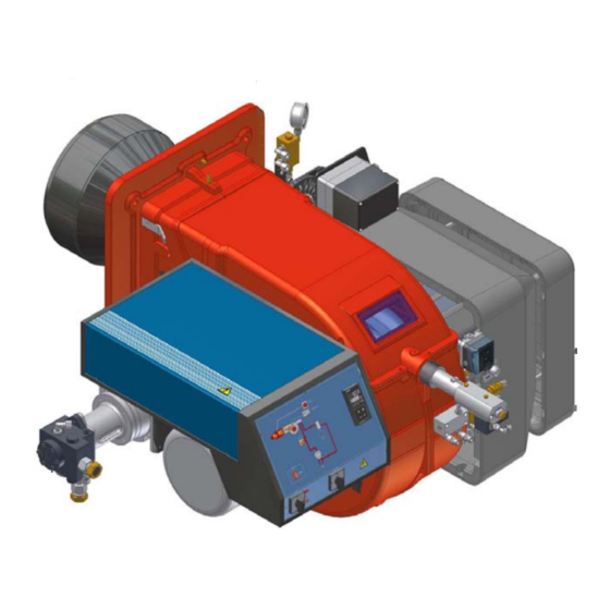
- Page 5 C.I.B. UNIGAS - M039144AD PARTE I: INSTALLAZIONE CARATTERISTICHE GENERALI I bruciatori di questa serie sono bruciatori monoblocco in fusione di alluminio con un range di potenza che va da 2550 a 13000 kW (in base al modello). Sono disponibili nella versione progressiva e modulante. Fig.
- Page 6 I bruciatori vengono identificati con tipi e modelli. L’identificazione dei modelli è descritta di seguito. Tipo RG1025 Modello G-. (5) (6) (1) BRUCIATORE TIPO RG1025 - RG1030 - RG1040 (2) COMBUSTIBILE G - Gasolio PR - Progressivo (3) REGOLAZIONE (Versioni disponibili)
- Page 7 Il bruciatore è idoneo solo se il punto di intersezione “A” delle due rette, ricade all’interno del campo di lavoro. I dati sono riferiti a condizioni standard: pressione atmosferica pari a 1013 mbar, temperatura ambiente pari a 15°C. Campi di lavoro RG1025 RG1030 RG1040 2000 3000 4000 5000 6000 7000 8000 9000 1 0000 1 1 000 1 2000 1 3000 ìPer ottenere la potenza in kcal/h, moltiplicare il valore in kW per 860.
- Page 8 Dimensioni di ingombro in mm Foratura caldaia consigliata e flangia bruciatore A(S*) A(L*) AA AC AD AE B(S*) B(L*) BB RR SS UU RG1025 1896 2090 377 1452 25 585 1546 1502 822 370 660 816 M16 651 460 460 265 80 142 1146 379 330...
- Page 9 C.I.B. UNIGAS - M039144AD MONTAGGI E ALLACCIAMENTI Trasporto e stoccaggio ATTENZIONE: le operazioni di seguito riportate vanno eseguite - sempre ed in via esclusiva - da personale spe- cializzato, nel pieno rispetto delle prescrizioni del manuale ed in conformità alle norme di sicurezza e salute vigenti.
- Page 10 C.I.B. UNIGAS - M039144AD Abbinamento del bruciatore alla caldaia I bruciatori descritti in questo manuale sono stati provati in camere di combustione rispondenti alla norma EN676, le cui dimensioni sono descritte nel diagramma . Nel caso in cui il bruciatore debba essere abbinato a caldaie con camera di combustione di diametro inferiore o di minore lunghezza di quelle descritte nel diagramma, contattare il Costruttore per verificare che esso si adatti all'applica- zione per cui è...
- Page 11 C.I.B. UNIGAS - M039144AD Collegamento della rampa gas pilota COSTRUTTORE INSTALLATORE Fig. 2 Legenda Bruciatore Valvole gas Pressostato di minima pressione gas Stabilizzatore di pressione con filtro incorporato Giunto antivibrante Valvola manuale di intercettazione La rampa pilota è già installata a bordo del bruciatore, deve essere eseguito il collegamento dal filtro con stabilizzatore alla rete di ali- mentazione del gas.
- Page 12 C.I.B. UNIGAS - M039144AD Collegamenti elettrici Rispettare le regole fondamentali di sicurezza, assicurarsi del collegamento all'impianto di messa a terra, non invertire i collegamenti di fase e neutro, prevedere un interruttore differenziale magneto-termico adeguato per l'allacciamento alla rete. ATTENZIONE: Prima di eseguire i collegamenti elettrici, assicurarsi di posizionare l’interruttore dell’impianto in posizione OFF e accertarsi che l’interruttore principale del bruciatore sia in posizione 0 (OFF - spento).
- Page 13 C.I.B. UNIGAS - M039144AD Schema di installazione tubazioni gasolio ATTENZIONE: LEGGERE SCRUPOLOSAMENTE LE AVVERTENZE RIPORTATE ALL’INIZIO DEL MANUALE. Dalla cisterna Alla cisterna Fig. 3 - Sistema bitubo La fornitura prevede il filtro e i flessibili, tutta la parte a monte del filtro e a valle del flessibile di ritorno, deve essere predisposta dall’utente.
- Page 14 C.I.B. UNIGAS - M039144AD Schemi esemplificativi di impianti di alimentazione gasolio Fig. 4 - Impianto a gravità - Impianto ad anello - Impianto in aspirazione Legenda Valvola manuale di intercettazione Filtro gasolio Pompa di alimentazione gasolio Valvola di non ritorno Flessibili gasolio Valvola di sfioro NOTA: negli impianti a gravità...
- Page 15 C.I.B. UNIGAS - M039144AD Principio di funzionamento della pompa Le pompe utilizzate possono essere installate sia in sistemi monotubo sia in quelli bitubo. Sistema monotubo: viene utilizzato un unico tubo che, partendo immediatamente sopra il fondo del serbatoio, raggiunge l’entrata della pompa.
- Page 16 C.I.B. UNIGAS - M039144AD Legenda Entrata G3/4 Attacco manometro G1/4 Attacco vacuometro per misura depressione in entrata G1/4 Alla valvola di regolazione pressione G3/4 N.B. Pompa con rotazione “C”. Regolatore di pressione Suntec TV Regolazione della pressione in mandata Rimuovere il dado cieco 1 e la guarnizione 2, svitare il dado di bloccaggio 4. Per aumentare la pressione, girare la vite di regolazione 3 in senso orario.
- Page 17 C.I.B. UNIGAS - M039144AD Circuito olio Il combustibile, alla pressione stabilita tramite il regolatore di pressione in mandata, viene spinto dalla pompa 1 all’ugello 3. L’elettroval- vola 2 blocca l’immissione di combustibile nella camera di combustione. L’ugello a riflusso è alimentato a pressione costante, mentre la pressione sulla linea di ritorno è...
- Page 18 La portata del gasolio viene regolata scegliendo un ugello (del tipo a riflusso) di dimensione adatta alla potenza della caldaia/utilizzo e tarando le pressioni di mandata e di ritorno secondo i valori riportati in tabella e nel diagramma di Fig. 18 (per la lettura delle pressione consultare i paragrafi successivi).
- Page 19 C.I.B. UNIGAS - M039144AD UGELLI BERGONZO Fig. 10...
- Page 20 C.I.B. UNIGAS - M039144AD Fig. 11...
- Page 21 Portata pompa Portata ugello Fig. 4 - Ugello Bergonzo B- Esempio con ugello da 850 kg/h Fig. 5...
- Page 22 C.I.B. UNIGAS - M039144AD Fig. 13...
- Page 23 C.I.B. UNIGAS - M039144AD REGOLAZIONI Regolazione - descrizione generale ATTENZIONE: prima di avviare il bruciatore, assicurarsi che le valvole manuali di intecettazione siano aperte. Assi- curarsi, inoltre, che l’interruttore generale di alimentazione sia chiuso. Prima di mettere in funzione il bruciatore accertarsi che la tubazione di ritorno alla cisterna non abbia occlusioni.
- Page 24 C.I.B. UNIGAS - M039144AD Accendere il bruciatore portando a ON l’interruttore principale A del bruciatore (vedi figura successiva): in caso di blocco (segna- lato dal LED B del quadro di controllo) premere il pulsante RESET (C) presente sul quadro del bruciatore (vedi figura successiva) - vedi “FUNZIONAMENTO”...
- Page 25 C.I.B. UNIGAS - M039144AD mensions Dimensions in SQM4... III IV Descrizione camme Alta fiamma Sosta e Accensione Bassa fiamma AUTO Limitazione corsa servocomando MAN-AUTO Siemens SQM10 Siemens SQM40 La pressione di alimentazione ugello è già pre-tarata in fabbrica e non deve essere cambiata. Solo se necessario, regolare la pres- sione di alimentazione (vedi relativo paragrafo) nel modo seguente: inserire un manometro nella posizione indicata in Fig.
- Page 26 C.I.B. UNIGAS - M039144AD 13 Per regolare punto-punto il settore variabile e definire il profilo della lamina, spostare prima il microinterruttore di bassa fiamma (camma III) appena sotto il massimo (90°); 14 portare il termostato TAB al minimo (per i bruciatori modulanti, consultare il relativo paragrafo) in modo che il servocomando agi- sca in chiusura;...
- Page 27 C.I.B. UNIGAS - M039144AD Regolazione della testa di combustione Per il funzionamento a potenza ridotta, allentare la vite VB e arretrare progressivamente la testa di combustione, verso la posizione "MIN.", ruotando in senso orario la ghiera VRT . Bloccare la vite VB a regolazione ultimata. Posizione testa “MAX”...
- Page 28 C.I.B. UNIGAS - M039144AD Pressostato di massima olio - taratura Il pressostato di massima sulla linea di ritorno dell'olio serve per monitorare che la pressione non ecceda un valore prefissato. Va tarato a non oltre la pressione massima accettabile sulla linea di ritorno. Tale valore è riportato nei dati tecnici. Una variazione di pressione sulla linea di ritorno ha influenza sui parametri di combustione;...
- Page 29 C.I.B. UNIGAS - M039144AD PARTE II: FUNZIONAMENTO LIMITAZIONI D'USO IL BRUCIATORE È UN APPARECCHIO PROGETTATO E COSTRUITO PER FUNZIONARE SOLO DOPO ESSERE STATO COR- RETTAMENTE ACCOPPIATO AD UN GENERATORE DI CALORE (ES. CALDAIA, GENERATORE ARIA CALDA, FORNO, ECC.), OGNI ALTRO USO E' DA CONSIDERARSI IMPROPRIO E QUINDI PERICOLOSO. L'UTENTE DEVE GARANTIRE IL CORRETTO MONTAGGIO DELL'APPARECCHIO AFFIDANDONE L'INSTALLAZIONE A PER- SONALE QUALIFICATO, E FACENDO ESEGUIRE LA PRIMA ACCENSIONE DA UN CENTRO ASSISTENZA AUTORIZZATO DALL'AZIENDA COSTRUTTRICE DEL BRUCIATORE.
- Page 30 C.I.B. UNIGAS - M039144AD FUNZIONAMENTO ATTENZIONE: prima di avviare il bruciatore, assicurarsi che le valvole manuali di intecettazione siano aperte. Assicurarsi, inoltre, che l’interruttore generale di alimentazione sia chiuso. Controllare che il bruciatore non sia in blocco (spia E accesa), in questo caso riattivare il bruciatore tramite il pulsante N che sblocca l’apparecchiatura di controllo fiamma.
- Page 31 C.I.B. UNIGAS - M039144AD PARTE III: MANUTENZIONE Almeno un volta all'anno eseguire le operazioni di manutenzione riportate nel seguito. Nel caso di servizio stagionale si raccomanda di eseguire la manutenzione alla fine di ogni stagione di riscaldamento; nel caso di servizio continuativo la manutenzione va eseguita ogni 6 mesi.
- Page 32 C.I.B. UNIGAS - M039144AD Manutenzione del filtro gasolio Per eseguire la manutenzione del filtro combustibile, procedere nel modo seguente: intercettare il tratto interessato; svitare la vaschetta. togliere la cartuccia filtrante, lavarla con benzina, se necessario, sostituirla; controllare gli O-ring di tenuta: se necessario sostituirli; rimontare la vaschetta e rimettere in funzione la linea.
- Page 33 C.I.B. UNIGAS - M039144AD Estrazione della lancia Per rimuovere la lancia, procedere nel modo seguente: rimuovere la testa di combustione, come descritto al paragrafo precedente; allentare la vite VB; sfilare la lancia con il portaugello; per il successivo rimontaggio eseguire in ordine inverso le operazioni sopra descritte. Fig.
- Page 34 C.I.B. UNIGAS - M039144AD Regolazione posizione dell’elettrodo e dell’ugello Al fine di garantire una buona accensione è necessario che siano rispettate le misure (espresse in mm) indicate in figura. Posizionare l’ugello rispetto alla testa di combustione, svitando la vite a brugola e muovendo la testa di combustione. Controllare l’elettrodo di accensione al termine delle operazioni.
- Page 35 C.I.B. UNIGAS - M039144AD Sostituzione dell’elettrodo di accensione ATTENZIONE: per non compromettere il funzionamento del bruciatore, evitare il contatto dell’elettrodo di accensione con parti metalliche (testa, boccaglio, ecc). Controllare la posizione dell’elettrodo dopo ogni intervento di manutenzione sulla testa di combustione. Per sostituire l’elettrodo di accensione procedere nel seguente modo: togliere la calotta del bruciatore;...
- Page 36 C.I.B. UNIGAS - M039144AD Fermo stagionale Per spegnere il bruciatore nel periodo di fermo stagionale, procedere nel modo seguente: portare l’interruttore generale del bruciatore in posizione 0 (OFF - spento) staccare la linea di alimentazione elettrica chiudere il rubinetto del combustibile della linea di distribuzione. Smaltimento del bruciatore In caso di rottamazione del bruciatore, seguire le procedure previste dalle leggi vigenti sullo smaltimento dei materiali.
- Page 37 C.I.B. UNIGAS - M039144AD SCHEMI ELETTRICI Consultare gli schemi elettrici allegati. ATTENZIONE 1 - Alimentazione elettrica 400V 50Hz 3N a.c. 2 - Non invertire fase con neutro 3 - Assicurare una buona messa a terra del bruciatore...
- Page 38 C.I.B. UNIGAS - M039144AD TABELLA PROBLEMI- CAUSE - SOLUZIONI - Funzionamento a gas * Non c’è alimentazione elettrica * Ripristine l’alimentazione * Interruttore principale aperto * Chiudere l’interruttore * Termostati aperti * Controllare i set point e i collegamenti dei termostati * Set point impostato male o termostato rotto * Reimpostare o sostituire il termostato * Mancanza di pressione del gas...
- Page 39 C.I.B. UNIGAS - M039144AD TABELLA PROBLEMI- CAUSE - SOLUZIONI - Funzionamento a gasolio * manca l’alimentazione elettrica * attendere che l’alimentazione elettrica venga ripristinata * Interruttore principale aperto * chiudere l’interruttore * Termostati aperti * controllare i set point e i collegmaneti dei termostati * Set-point impostato male o termostato rotto * impostare o sostituire il termostato * mancanza pressione gas...
- Page 40 APPENDICE Con LAL2..: Poco dopo l’inizio del tempo di preventilazione, il pressostato APPARECCHIATURA DI CONTROLLO FIAMMA SIEMENS LAL2.25 aria deve commutare dal morsetto 13 al morsetto 14. In caso contrario l’apparecchio provocherebbe un arresto di blocco (parte il controllo della Impiego pressione aria).
- Page 41 combustibile è immediatamente interrotto. Nello stesso tempo, il program- Totale max. AC 5 A matore resta immobile, come l’indicatore di posizione dell’interruttore. Il Fusibile incorporato T6,3H250V to IEC 127 simbolo visibile sul disco di lettura dell’indicatore indica il tipo di anomalia: Fusibile esterno max.
- Page 42 Diagramma del programmatore Uscite di comando t3 n t3" t1 6 V II V III X II t10* X III X IV Indicazione di posizione dell’interruzione...
- Page 44 C.I.B. UNIGAS S.p.A. Via L.Galvani, 9 - 35011 Campodarsego (PD) - ITALY Tel. +39 049 9200944 - Fax +39 049 9200945/9201269 web site: www.cibunigas.it - e-mail: cibunigas@cibunigas.it Le informazioni contenute in questo documento sono puramente indicative e non impegnative. L’azienda si riserva la facoltà...
- Page 45 CIB UNIGAS 600V CONTROLLER USER’S MANUAL COD. M12925CA Rel 1.2 08/2014 SOFTWARE VERSION 1.0x code 80379 / Edition 01 - 06/2012 1 • INSTALLATION 2 • TECHNICAL SPECIFICATIONS Display 2x4 digit green, high display 10 and 7mm Keys 4 of mechanical type (Man/Aut, INC, DEC, F) •...
- Page 46 3 • DESCRIPTION OF FACEPLATE Function indicators Indication of output states Indicates modes of operation OUT 1 (AL1); OUT 2 (OPEN); OUT 3 (CLOSED) MAN/AUTO = OFF (automatic control) ON (manual control) PV Display: Indication of process variable Error Indication: LO, HI, Sbr, Err PRE-HEATING = ON (running) LO= the value of process variable is <...
- Page 47 5 • “EASY” PROGRAMMING and CONFIGURATION S4 Jumper THE EASY CONFIGURATION (Pro=0...12) IS SUITABLE FOR (CPU) VERSIONS WITH AL1/OPEN/CLOSED LEVEL 1 MENU P.V. / S.V. Process variable P.V. / S.V. (PV display) Work Setpoint (SV display) or control output value with controller in manual Password Local Setpoint...
- Page 48 • InFo Display Information display Software version 0 No Error Self diagnostic 1 Lo error code 2 Hi 3 ERR 4 SBR OUTPUT 2 OUTPUT 3 SERIAL COMMUNICATION 0 = None 0 = None 0 = None +8 error OUT2 card recognition 1 = Relay 1 = Relay +16 error OUT3 card recognition...
- Page 49 • InP Input settings S, R range 0...1750°C; error < 0.2% f.s. (t > 300°C) / for other sp. r 0 default (remote setpoint present) Def. remote setpoint range; error < 0.5% f.s. error < 0.2% f.s. (t > -150°C) range 44...1800°C;...
- Page 50 • Out Output settings Select a1. r reference signal for alarm1 AL.1.r AL.x.r Variable to be compared PV (process variable) AL.1.t AL.x.t Direct (high limit) Absolute or Normal 2/3 for a1. t Inverse (low limit) relative to Symmetrical alarm 1 active setpoint (window) direct...
- Page 51 • Prot Protection code Prot Display Modification SP, Hy.P, Hy.n, AL.2, AL.3, PoS, OuP, INF SP, Hy.P , Hy.n, AL.2, AL.3, PoS SP, Hy.P, Hy.n, AL.2, AL.3, PoS, OuP, INF SP, OuP, INF + 4 to disable InP, Out + 8 to disable CFG + 16 to disable SW “power-up - power down”...
- Page 52 ld. 1 Function of LEDs Val. Function none MAN/AUTO controller ld. 2 HOLD Selftuning enabled Autotuning enabled ld. 3 Error present Softstart running Set point gradient running Pre-heating running + 16 LED flashes if active • Lin Custom linearization for main input Step 0 beginning Display limits s.
- Page 53 7 • CONSENT FOR BURNER AL1 Obtain burner consent by configuring alarm 1 as inverse deviation with positive hysteresis Hy.P and negative hysteresis Hy.n 8 • PRE-HEATING FUNCTION Enable the pre-heating function by setting parameters GS.0, Ht.0, GS.1 other than zero. It consists of three phases that are activated sequentially at firing: - Ramp 0 phase Enabled by setting GS.0 >...
- Page 54 9 • ADJUSTMENT WITH MOTORIZED VALVE In an adjustment process the adjustment valve has the function of varying fuel delivery (frequently corresponding to the thermal energy introduced into the process) in relation to the signal coming from the controller. For this purpose it is provided with an actuator able to modify its opening value, overcoming the resistances produced by the fluid passing inside it.
- Page 55 Valve control modes With the controller in manual, the setting of parameter At.y ≥ 8 allows direct control of the valve open and close commands through the keyboard Increments and Decrements on the front seats. V0 - for floating valve without potentiometer Model V0 have similar behaviour: every manoeuvre request greater than the minimum impulse t.Lo is sent to the actuator by means of the OPEN/CLOSE relays;...
- Page 56 11 • MANUAL TUNING A) Enter the setpoint at its working value. B) Set the proportional band at 0.1% (with on-off type setting). C) Switch to automatic and observe the behavior of the variable. It will be similar to that in the figure: Process D) The PID parameters are calculated s follows: Proportional band Variable...
- Page 57 15 • ACCESSORIES • Interface for instrument configuration Kit for PC via the USB port (Windows environment) for GEFRAN instruments configuration: KIT PC USB / RS485 o TTL Lets you read or write all of the parameters • A single software for all models •...
- Page 59 21/06/2012 rev. 0 Set-up for 600V RRR0-1-T73 regulator Set up for temperature probe Pt100 (ex Siemens QAE2120 130°C max.) The regulator comes out of the factory preset with the corresponding values of the Siemens RWF40.000 and RWF50.2x Verify wiring of the sensor Regulation of the set-point = 80 It can be modified by using arrows "up"...
- Page 60 A1.r … A1.t 3 (operating mode AL1 =inverse-relative-normal) … rL.1 2 (AL1) rL.2 18 (open) rL.3 19 (close) A.ty 9 (type of servocontrol command) Ac.t 12 (servocontrol running time: SQN72.4…/STA12..=12; SQM40.265=30) t_Lo t_Hi t.on t.oF dE.b 0,1 (dead zone in % of end scale) 99 then push and keep pushed F until visualization of Hrd …...
- Page 61 Set up for temperature probe Pt100 for high temperature (350°C max.) Verify wiring of the sensor Regulation of the set-point = 80 It can be modified by using arrows "up" and "down". By pushing F you go to parameters: Hy.P 10 (hysteresis positive for output 1 terminals 21-22 (ex Q13-Q14) Hy.n -5 (hysteresis negative for output 1 terminals 21-22 (ex Q13-Q14)
- Page 62 A1.r … A1.t 3 (mode AL1 =inverse-relative-normal) … rL.1 2 (AL1) rL.2 18 (open) rL.3 19 (close) A.ty 9 (type of servocontrol command) Ac.t 12 (servocontrol running time: SQN72.4…/STA12..=12; SQM40.265=30) t_Lo t_Hi t.on t.oF dE.b 0,1 (dead zone in % of end scale) 99 then push and keep pushed F until visualization of Hrd …...
- Page 63 Set up for pressure transmitter 2 wires signal 4÷20mA With pressure transmitters first we need to enable their power supply: remove the part as shown below, then, on the CPU unit, move the bridge from Pt100 to +Vt IN/OUT cards Signal selection on terminal 3 Verify wiring of the sensor...
- Page 64 …. 44 (4÷20mA) … dP_S 2 (decimals num.) Transmitter 1,6bar 3bar 10bar 16bar 25bar 40bar Lo.S 0,00 0,00 0,00 0,00 0,00 0,00 min. sensor scale Hi.S 1,60 3,00 10,00 16,00 25,00 40,00 max sensor scale offset of input correction Lo.L 0,00 0,00 0,00...
- Page 65 Set -up for thermocouples type Verify wiring of the sensor Regulation of the set-point = 80 It can be modified by using arrows "up" and "down". By pushing F you go to parameters: Hy.P 10 (hysteresis positive for output 1 terminals 21-22 (ex Q13-Q14) Hy.n -5 (hysteresis negative for output 1 terminals 21-22 (ex Q13-Q14) Keep pushing F until you see PASS, release F and through the arrows set 99, push F and visualize Pro...
- Page 66 A1.r … A1.t 3 (mode AL1 =inverse-relative-normal) … rL.1 2 (AL1) rL.2 18 (open) rL.3 19 (close) A.ty 9 (type of servocontrol command) Ac.t 12 (servocontrol running time: SQN72.4…/STA12..=12; SQM40.265=30) t_Lo t_Hi t.on t.oF dE.b 0,1 (dead zone in % of end scale) 99 then push and keep pushed F until visualization of Hrd …...
- Page 69 RWF50.2x & RWF50.3x User manual M12922CB Rel.1.0 07/2012...
- Page 70 DEVICE INSTALLATION Install the device using the relevant tools as shown in the figure. To wire the device and sensors, follow the instructions on the burner wiring diagram.
- Page 71 FRONT PANEL NAVIGATION MENU Parameter level Basic display User Level - Opr SP1 or SP2 (editable) dSP readable and editable through bin1 = 2 InP1 or y (only display) Parameter Level - PArA HYS1 , HYS2 , HYS3 Pb1, dt, rt, db, tt Next parameter Main navigation...
- Page 72 RWF5 is preset good for 90% of applications. However, you can set or edit parameters as follow: Set-point: set or modification: When the burner is in stand-by, (safety loop open, that is terminals 3-4/T1-T2 on the 7 pole plug open) push the Enter button: on the lower display (green) Opr appears;...
- Page 73 Setting the kind of sensor to be connected to the device: push the Enter button: on the lower display (green) Opr appears. Using the up and down arrows find ConF. Push Enter to confirm. Now on the green display the group InP appears. Push Enter and InP1 is displaied. Enter to confirm. ...
- Page 74 ConF > Cntr Parameter Value Description CtYP 1 = 3-position controller (open-stop-close only RWF50.2) controller type 2 = continuative action controller (only RWF50.3) CACt 1 = heating controller control action 0 = cooling controller least value of the set-point limitation prevents entry of values outside the defined set-point range -1999..0..+9999 range...
- Page 75 ConF > OutP (parameter under group only for RWF50.3) Parameter Value Description FnCt 1 = analog input 1 doubling with possibility to convert tipo di controllo (depending on par SiGn) 4 = modulation controller SiGn physical output signal (terminals A+, A-) type of output signal 0 = 0÷20mA 1 = 4÷20mA...
- Page 76 Manual control : in order to manual change the burner load, while firing keep pushing the ESC button for more than 5 s; on the lower green display Hand appears. using the UP and DOWN arrows, the load varies. ...
- Page 77 Electric connection : With 7 pins connector version With terminals version Matches terminals between RWF50.2 and RWF40.0x0...
- Page 78 Parameters summarising for RWF50.2x: Conf Conf Navigation menù Inp1 Cntr diSP PArA Types of probe SEn1 OFF1 SCL1 SCH1 Unit dECP Pb. 1 dt HYS1 (*) HYS3 (*) SP1 (*) Siemens QAE2120… needless needless 80 350 (#) 80 °C Siemens QAM2120.. needless needless 80 350 (#)
- Page 79 APPENDIX: PROBES CONNECTION To assure the utmost comfort, the control system needs reliable information, which can be obtained provided the sensors have been installed correctly. Sensors measure and transmit all variations encountered at their location. Measurement is taken based on design features (time constant) and according to specific operating conditions.With wiring run in raceways, the sheath (or pipe) containing the wires must be plugged at the sensor's terminal board so that currents of air cannot affect the sensor's measurements.
- Page 80 Duct or pipe sensors Installing pressure sensors A - installation on ducts carrying fluids at max. temperature 80°C Installing temperature sensors For measuring outlet air: B - installation on ducts at temperature over 80°C and for refrigerants after delivery fan or C - installation on ducts at high temperatures: ...
- Page 81 Immersion or strap-on sensors Immersion probes installation Sensors must be installed on the stretch of pipe in which fluid circulates all the time. The rigid stem (sensing element doing the measuring) must be inserted by at least 75mm and must face the direction of flow. Recommended locations: on a bend or on a straight stretch of pipe but tilted by 45°...
- Page 82 Duct pressure switches and sensors Installing differential pressure probes for air Basic principles Measuring static pressure(i.e. pressure exerted by air on pipe walls) A - Control a filter (clogging) Measuring dinamic pressure B - Control a fan (upstream/downstream) Kg/m , specific weight of air m/s, air speed 9.81 m/s gravity acceleration...
- Page 83 Spare parts Description Code Modulator RWF50.2 (uscita a 3 punti - apri, fermo, chiudi) 2570148 2570149 Modulator RWF50.3 (uscita continua 0÷20mA, 4÷20mA, 0÷10V) Temperature probe Siemens QAE2120.010A (30÷130°C) 2560101 2560135 Temperature probe Siemens QAM2120.040 (-15÷+50°C) 2560188 Thermoresistor Pt1000 ø6mm L100mm (30÷130°C) Thermoresistor Pt1000 ø10mm L200mm (0÷350°C) 2560103 2560145...
- Page 84 Note: Specifications and data subject to change. Errors and omissions excepted.
- Page 85 KM3 Modulator USER MANUAL M12927CA Rel.1.0 10/2020...
- Page 86 M12927CA MOUNTING...
- Page 87 M12927CA DISPLAY Y AND KEY onsent to the burner is rned off OUTP UT LEDs ON (o out1) - Consen nt to the burne ▲ - (o out2) Output i ncrease ▼ - (o out3) Output d decrease ● - (ou ut4) Modulato r is powered o perator Mode...
- Page 88 M12927CA CONNECTIONS DIAGRAM Probe connection: • PT1000/NTC/PTC: between terminal 3 and 2 • PT 100: between terminal 3 and 2 with terminal 1 • Passive pressure probe 0/4-20 mA: between terminal 4 ( + ) e 1 ( - ) Note: out4 must be activated ( IO4F must be setted to ON ) •...
- Page 89 M12927CA SETPOINT AND HYSTERESIS CONFIGURATION (SP, AL1, HAL1 parameters) Push the button to enter into the setpoint configuration: SP setpoint value change: increase decrease 2480 Confirm / Next AL1 parameter value change: increase decrease Confirm / Next HAL1 HAL1 parameter value change: increase decrease Confirm / Next Back to the first parameter To return to normal mode, press the key for 3 seconds or wait the 10s timeout...
- Page 90 M12927CA LIMITED ACCESS LEVEL Proceed as follows to change some parameters that are not visible in standard user mode: Press the key for Password = 20 3 seconds Access to parameter: Increase the displayed value Decrease the displayed value Confirm and go to next parameter Param Description...
- Page 91 M12927CA...
- Page 92 M12927CA CONFIGURATION How to access configuration level The configuration parameters are collected in various groups. Every group defines all parameters related with a specific function (e.g.: control, alarms, output functions). Push the button for more than 5 seconds. The upper display will show PASS while the lower display will show 0.
- Page 93 M12927CA Safety output value -100... 100 io4.F I/O4 function selection on = Out4 will be ever ON (used as a transmitter power supply) ,out4 = Uscita 4 (Used as digital output 4), dG2c = Digital input 2 for contact closure, dG2U = Digital input 2 driven by 12... 24 diF1 Digital input 1 function oFF = Not used,...
- Page 94 M12927CA windows SE.br = Sensor Break LodE = Deviation low alarm (relative) HidE = Deviation high alarm (relative) LHdo = Relative band alarm in alarm out of the band LHdi = Relative band alarm in alarm inside the band Alarm 1 function 0...
- Page 95 M12927CA AL3 Group - alarm 3 parameters Param Description Values Liv N° Default AL3t Alarm 3 type nonE = Alarm not used nonE LoAb = Absolute low alarm HiAb = Absolute high alarm LHAo = Windows alarm in alarm outside the windows LHAI = Windows alarm in alarm inside the windows...
- Page 96 M12927CA SELF Self tuning enabling no = The instrument does not perform the self- tuning YES = The instrument is performing the self- tuning Proportional band 1... 9999 (E.U.) page 7 Integral time 0 (oFF) ... 9999 (s) page 7 Derivative time 0 (oFF) ...
- Page 97 M12927CA AAc = Alarm reset ASi = Alarm acknowledge chSP = Sequential set point selection St.by = Stand by mode. The first press puts the instrument in stand by mode while a second one puts the instrument in Auto mode. Str.t = Timer run/hold/reset P.run = Program run P.rES = Program reset...
- Page 98 M12927CA con Group - Consumption parameters Param Description Values N° Default Co.tY Count type oFF = Not used 1 = Instantaneous power (kW) 2 = Power consumption (kW/h) 3 = Energy used during program execution. This measure starts from zero when a program runs end stops at the end of the program.
- Page 99 M12927CA OPERATIVE MODES When the instrument is powered, it starts immediately to work according to the parameters values loaded in its memory. The instrument behaviour and its performance are governed by the value of the stored parameters. At power ON the instrument can start in one of the following mode depending on its configuration: Automatic Mode In Automatic mode the instrument drives automatically the control output according to the parameter value set and the set point/measured value.
- Page 100 M12927CA Direct set point modification This function allows to modify rapidly the set point value selected by [83] A.SP (selection of the active Set point) or to the set point of the segment group (of the programmer) currently in progress. Push button.
- Page 101 M12927CA ERROR MESSAGES The upper display shows the OVER-RANGE and UNDERRANGE conditions with the following indications: Over-range: Under-range The sensor break will be signalled as an out of range: Note: When an over-range or an under-range is detected, the alarms operate as in presence of the maximum or the minimum measurable value respectively.
- Page 102 KM3 Modulator USER MANUAL M12927CA Rel.1.0 10/2020...
- Page 103 M12927CA MOUNTING...
- Page 104 M12927CA DISPLAY Y AND KEY onsent to the burner is rned off OUTP UT LEDs ON (o out1) - Consen nt to the burne ▲ - (o out2) Output i ncrease ▼ - (o out3) Output d decrease ● - (ou ut4) Modulato r is powered o perator Mode...
- Page 105 M12927CA CONNECTIONS DIAGRAM Probe connection: • PT1000/NTC/PTC: between terminal 3 and 2 • PT 100: between terminal 3 and 2 with terminal 1 • Passive pressure probe 0/4-20 mA: between terminal 4 ( + ) e 1 ( - ) Note: out4 must be activated ( IO4F must be setted to ON ) •...
- Page 106 M12927CA SETPOINT AND HYSTERESIS CONFIGURATION (SP, AL1, HAL1 parameters) Push the button to enter into the setpoint configuration: SP setpoint value change: increase decrease 2480 Confirm / Next AL1 parameter value change: increase decrease Confirm / Next HAL1 HAL1 parameter value change: increase decrease Confirm / Next Back to the first parameter To return to normal mode, press the key for 3 seconds or wait the 10s timeout...
- Page 107 M12927CA LIMITED ACCESS LEVEL Proceed as follows to change some parameters that are not visible in standard user mode: Press the key for Password = 20 3 seconds Access to parameter: Increase the displayed value Decrease the displayed value Confirm and go to next parameter Param Description...
- Page 108 M12927CA...
- Page 109 M12927CA CONFIGURATION How to access configuration level The configuration parameters are collected in various groups. Every group defines all parameters related with a specific function (e.g.: control, alarms, output functions). Push the button for more than 5 seconds. The upper display will show PASS while the lower display will show 0.
- Page 110 M12927CA Safety output value -100... 100 io4.F I/O4 function selection on = Out4 will be ever ON (used as a transmitter power supply) ,out4 = Uscita 4 (Used as digital output 4), dG2c = Digital input 2 for contact closure, dG2U = Digital input 2 driven by 12... 24 diF1 Digital input 1 function oFF = Not used,...
- Page 111 M12927CA windows SE.br = Sensor Break LodE = Deviation low alarm (relative) HidE = Deviation high alarm (relative) LHdo = Relative band alarm in alarm out of the band LHdi = Relative band alarm in alarm inside the band Alarm 1 function 0...
- Page 112 M12927CA AL3 Group - alarm 3 parameters Param Description Values Liv N° Default AL3t Alarm 3 type nonE = Alarm not used nonE LoAb = Absolute low alarm HiAb = Absolute high alarm LHAo = Windows alarm in alarm outside the windows LHAI = Windows alarm in alarm inside the windows...
- Page 113 M12927CA SELF Self tuning enabling no = The instrument does not perform the self- tuning YES = The instrument is performing the self- tuning Proportional band 1... 9999 (E.U.) page 7 Integral time 0 (oFF) ... 9999 (s) page 7 Derivative time 0 (oFF) ...
- Page 114 M12927CA AAc = Alarm reset ASi = Alarm acknowledge chSP = Sequential set point selection St.by = Stand by mode. The first press puts the instrument in stand by mode while a second one puts the instrument in Auto mode. Str.t = Timer run/hold/reset P.run = Program run P.rES = Program reset...
- Page 115 M12927CA con Group - Consumption parameters Param Description Values N° Default Co.tY Count type oFF = Not used 1 = Instantaneous power (kW) 2 = Power consumption (kW/h) 3 = Energy used during program execution. This measure starts from zero when a program runs end stops at the end of the program.
- Page 116 M12927CA OPERATIVE MODES When the instrument is powered, it starts immediately to work according to the parameters values loaded in its memory. The instrument behaviour and its performance are governed by the value of the stored parameters. At power ON the instrument can start in one of the following mode depending on its configuration: Automatic Mode In Automatic mode the instrument drives automatically the control output according to the parameter value set and the set point/measured value.
- Page 117 M12927CA Direct set point modification This function allows to modify rapidly the set point value selected by [83] A.SP (selection of the active Set point) or to the set point of the segment group (of the programmer) currently in progress. Push button.
- Page 118 M12927CA ERROR MESSAGES The upper display shows the OVER-RANGE and UNDERRANGE conditions with the following indications: Over-range: Under-range The sensor break will be signalled as an out of range: Note: When an over-range or an under-range is detected, the alarms operate as in presence of the maximum or the minimum measurable value respectively.
Need help?
Do you have a question about the RG1025 and is the answer not in the manual?
Questions and answers