Table of Contents
Advertisement
Quick Links
Advertisement
Table of Contents

Subscribe to Our Youtube Channel
Related Manuals for PCB Piezotronics IMI SENSORS 685A11


Summary of Contents for PCB Piezotronics IMI SENSORS 685A11
- Page 1 Model 685A11 Electronic Vibration Switch Installation and Operating Manual For assistance with the operation of this product, contact PCB Piezotronics, Inc. Toll-free: 800-959-4464 24-hour SensorLine: 716-684-0001 Fax: 716-684-3823 E-mail: imi@pcb.com Web: www.imi-sensors.com...
- Page 2 Returning Equipment – Following the equipment to PCB Piezotronics for these procedures will insure that your repair. User servicing or repair is not returned materials are handled in the recommended and, if attempted, may most expedient manner.
- Page 3 PCB Piezotronics, Inc. Warranty – All equipment and repair 3425 Walden Ave. services provided by PCB Piezotronics, Depew, NY 14043 USA Inc. are covered by a limited warranty Toll-free: (800) 828-8840 against defective...
- Page 4 Model 685AX1 Electronic Vibration Switch Operating Guide with Enclosed Warranty Information 3425 Walden Avenue, Depew, New York 14043-2495 Phone (716) 684-0003 Fax (716) 684-3823 Toll Free Line 1-800-959-4IMI MANUAL NUMBER: 25109 MANUAL REVISION: A...
-
Page 5: Table Of Contents
Table of Contents Introduction........................Page 3 General Features Specifications ........................Page 4 Installation and Wiring ..................... Page 5 Configuring the 685AX1 ....................Page 7 ESD Sensitivity........................ Page 8 Ordering Information......................Page 9 Warranty/Servicing Warranty, Service & Return Procedure ................. Page 10 Customer Service ...................... -
Page 6: Introduction
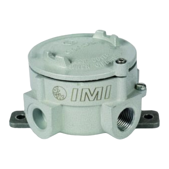
Introduction The Model 685AX1 is an Electronic Vibration Switch designed to monitor vibration levels and trip an alarm when a specified limit is exceeded. An onboard accelerometer with precision electronics insures reliability and accuracy. The device comes standard in an Explosion Proof Enclosure. General Features ... -
Page 7: Specifications
Specifications Power Supply Voltage: …… 10-30Vdc Power Supply Current: …… 100mA max. Sensor Type: …… Piezoelectric Sensing Element Vibration Range: …… 0-10g-peak (0-1ips Optional) -3dB Frequency Response: …… 3Hz to 1Khz (180 – 60,000cpm) ... -
Page 8: Installation And Wiring
Installation and Wiring Installation The Model 685AX1 is designed to be mounted directly on the equipment to be monitored via a supplied mounting bracket. Use grease between all surfaces to insure specified frequency response, otherwise performance will be degraded. Dimension Drawing Inch (mm) WARNING AC and DC input signals and power supply voltages could be hazardous. - Page 9 Connector and Pinout Diagram The 685AX1 uses plug-in type screw terminal connectors for all input and output connections. Strip off 0.3” (8mm) of insulation from the connection wire ends. Remove the terminal block from the enclosure, feed the wire through the access ports, and terminate the wire in the correct location. Do not exceed a torque of .05 Nm (0.04 lbft).
-
Page 10: Configuring The 685Ax1
Configuring the 685AX1 Internal Diagram The internal diagram displays the location of the control features for the 685AX1. The alarm setpoint is adjusted via a single turn potentiometer. Relay operation is selected for either latch or continuous. And the device can be locally reset after an alarm condition has been corrected. -
Page 11: Esd Sensitivity
Warning 2 – ESD sensitivity This equipment is designed with user safety in mind; however, the protection provided by the equipment may be impaired if the equipment is used in a manner not specified by PCB Piezotronics, Inc. Caution 1 – ESD sensitivity Cables can kill your equipment. -
Page 12: Ordering Information
Ordering Information IMI Part Number: 685A X 1 Vibration Range and Relay Characteristics* ) peak – standard model with 5Amp Form C Relay (1) 0-10g (98.1m/s 0-1ips (25.4mm/s) peak with 5Amp Form C Relay (1) 0-10g (98.1m/s ) peak, alarm under limit operation, with 5Amp Form C Relay (1) 0-1ips (25.4mm/s) peak, alarm under limit operation, with 5Amp Form C Relay (1) 0-10g (98.1m/s ) peak, with 1Amp Form C Relay (2) -
Page 13: Warranty, Service & Return Procedure
Warranty IMI instrumentation is warranted against defective material and workmanship for 1 year unless otherwise expressly specified. Damage to instruments caused by incorrect power or misapplication, is not covered by warranty. If there are any questions regarding power, intended application, or general usage, please consult with your local sales contact or distributor. -
Page 14: Customer Service
Customer Service IMI, a division of PCB Piezotronics, guarantees Total Customer Satisfaction. If, at any time, for any reason, you are not completely satisfied with any IMI product, IMI will repair, replace, or exchange it at no charge. You may also choose to have your purchase price refunded.
Need help?
Do you have a question about the IMI SENSORS 685A11 and is the answer not in the manual?
Questions and answers